Strong turning tool with adjustable chip breaking block and use method thereof

A chip-breaking and powerful technology, which is applied in the direction of lathe tools, turning equipment, tool holder accessories, etc., can solve the problem of limited position adjustment function of turning tool chip breaking block, insufficient position stability of turning tool chip breaking block, cutting tool The rod cannot be used multiple times, etc., to achieve the effect of improving the service life, saving man-hours, and cutting the material of the cutter rod

Pending Publication Date: 2017-08-29
FUZHOU UNIV
View PDF4 Cites 4 Cited by
  • Summary
  • Abstract
  • Description
  • Claims
  • Application Information

AI Technical Summary

Problems solved by technology

In the mechanical clamping structure tool, the most difficult problem is that the chip breaker cannot be adjusted, and if it is welded, it will cause defects
The blade cannot be used multiple times
cause a lot of waste
[0003] The existing chip breaking blocks for turning tools basically need to modify the original structure on the turning tool before installing the chip breaking block on the turning tool, which has problems such as high processing cost and long production cycle. In addition, the current The position adjustment function of the turning tool chip breaker is limited, and the position stability of the turning tool chip breaker is not enough

Method used


Image

  • Strong turning tool with adjustable chip breaking block and use method thereof
  • Strong turning tool with adjustable chip breaking block and use method thereof
  • Strong turning tool with adjustable chip breaking block and use method thereof

Examples


Embodiment Construction

[0031] The present invention will be described in detail below in conjunction with the accompanying drawings and specific embodiments. This embodiment is carried out on the premise of the technical solution of the present invention, and detailed implementation and specific operation process are given, but the protection scope of the present invention is not limited to the following embodiments.

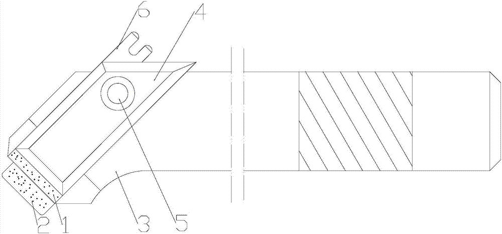
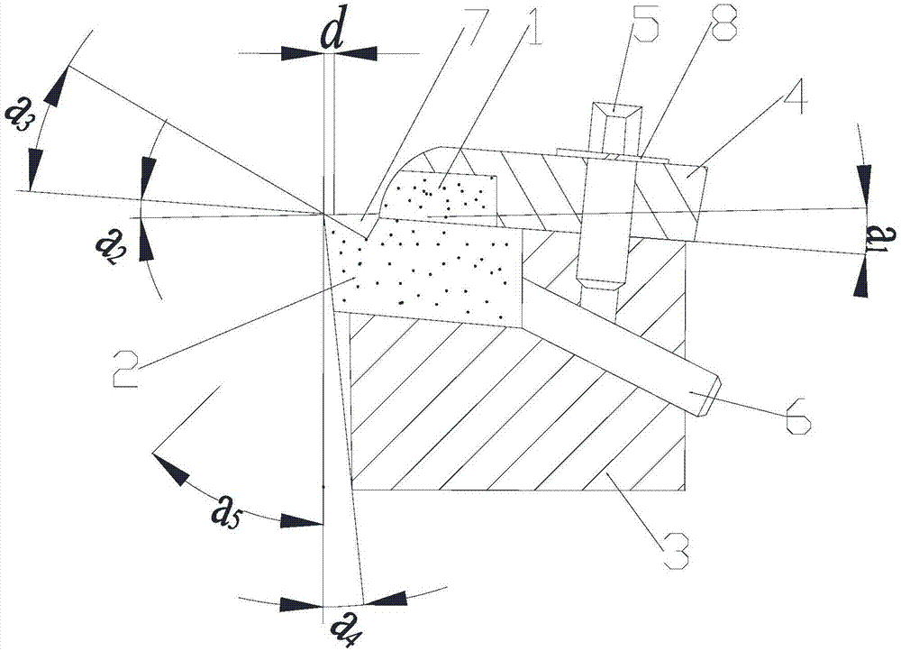
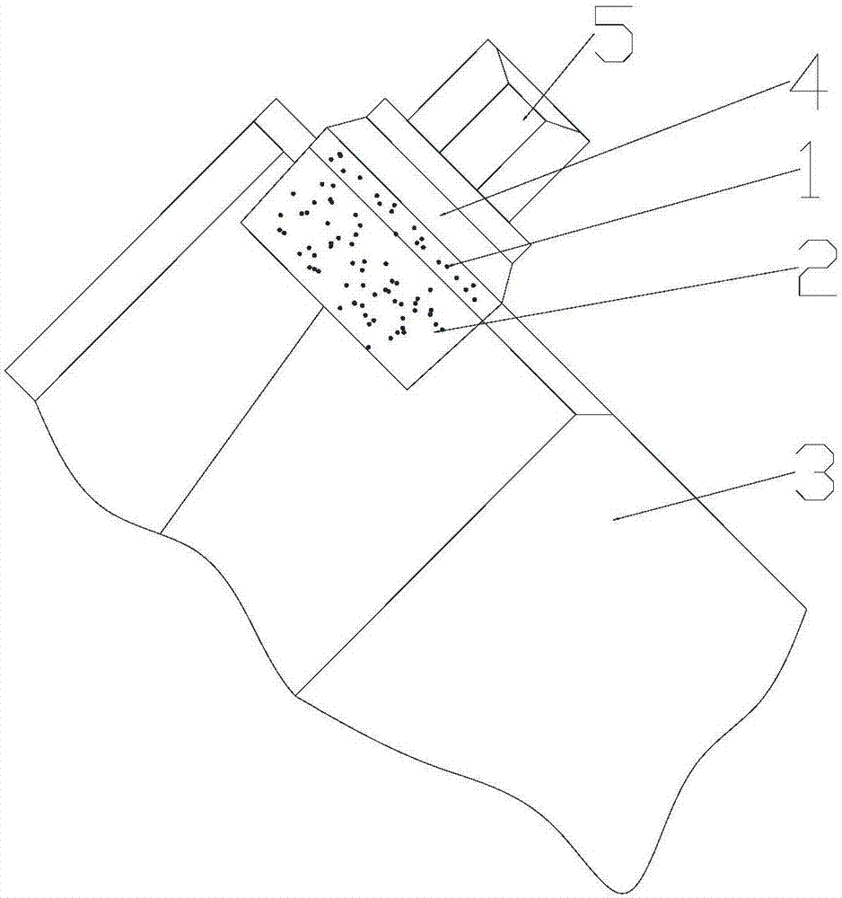
[0032] Such as Figure 1-Figure 3 As shown, a powerful turning tool with an adjustable chip breaking block includes a chip breaking block 1, a blade 2, a tool bar 3, a pressing piece 4, a clamping screw 5 and an adjusting screw 6, and the upper end surface of the tool bar 3 end is set There are parallelogram blade installation slots and adjustment screw holes, the upper surface of the end of the knife bar 3 is inclined downward from front to rear, and is parallel to the lower side of the blade installation slot, the front side and upper side of the blade installation slot Both openin...


PUM


Abstract

The invention relates to a strong turning tool with an adjustable chip breaking block and a use method thereof. The strong turning tool comprises the chip breaking block, a blade, a tool bar, a pressing piece, a clamping and fixing screw and an adjusting screw. A blade installation groove which is each in a parallelogram shape and an adjusting screw hole are formed in the upper end surface of the end of the tool bar, openings are formed in the front end surface and the upper side surface of the blade installation groove, and the blade is installed in the blade installation groove; the adjusting screw hole communicate with the rear side surface of the blade installation groove, the pressing piece is arranged at the end of the tool bar, and a chip breaking block installation groove is formed in the lower end surface of the end of the pressing piece; the chip breaking block is installed in the chip breaking block installation groove, and the bottom surface of the chip breaking block abuts against the top surface of the blade; and the clamping and fixing screw penetrates through the pressing piece and is connected with the tool bar, and the adjusting screw penetrates through the adjusting screw hole and then abuts against the blade. Compared with the prior art, the strong turning tool with the adjustable chip breaking block and the use method thereof overcome the defect that a chip breaking block of an ordinary tool cannot be adjusted, so that adjusting of the chip breaking block is achieved, and after being sharpened, the blade can also be adjusted; and the tool bar can also be repeatedly used, tool bar materials are saved, and the working time for sharpening and tool bar forging is greatly saved.

Description

technical field [0001] The invention relates to a turning tool, in particular to a powerful turning tool with an adjustable chip breaking block and a using method thereof. Background technique [0002] Whether the chip breaking is reliable or not has a great impact on normal production and operator safety. In the cutting process, the broken chips will splash and hurt people, and easily damage the machine tool; while the long strip-shaped chips will wrap around the workpiece or the tool, which is easy to scratch the workpiece, cause tool damage, and even affect the safety of workers. For automatic processing machine tools such as CNC machine tools (machining centers), due to the large number of tools and the close relationship between the tool holder and the tools, the problem of chip breaking is even more important. As long as one of the tools is not reliable for chip breaking, it may damage the machine tool. Automatic circulation, or even destroy the normal operation of th...

Claims


Application Information

Patent Timeline
Patent Type & Authority Applications(China)
IPC IPC(8): B23B27/22
CPCB23B27/22
Inventor 陈功振
Owner FUZHOU UNIV
Why Eureka
Try Eureka