Device for making a groove in cardboard blanks

A technology for cardboard blanks and equipment, which is applied to the field of equipment for grooving cardboard blanks, can solve the problems of inability to adjust the groove angle and the existence of adjustment costs, and achieve the effect of simple pivoting.

Active Publication Date: 2014-05-21
KOLBUS
View PDF7 Cites 3 Cited by
  • Summary
  • Abstract
  • Description
  • Claims
  • Application Information

AI Technical Summary

Problems solved by technology

However, the adjustment costs for the cardboard hold-down device and the chipping device still remain, and the groove angle cannot be adjusted independently of each other

Method used


Image

  • Device for making a groove in cardboard blanks
  • Device for making a groove in cardboard blanks
  • Device for making a groove in cardboard blanks

Examples


Embodiment Construction

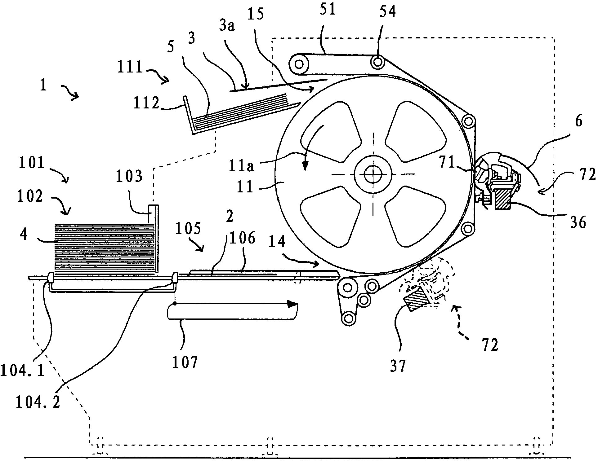
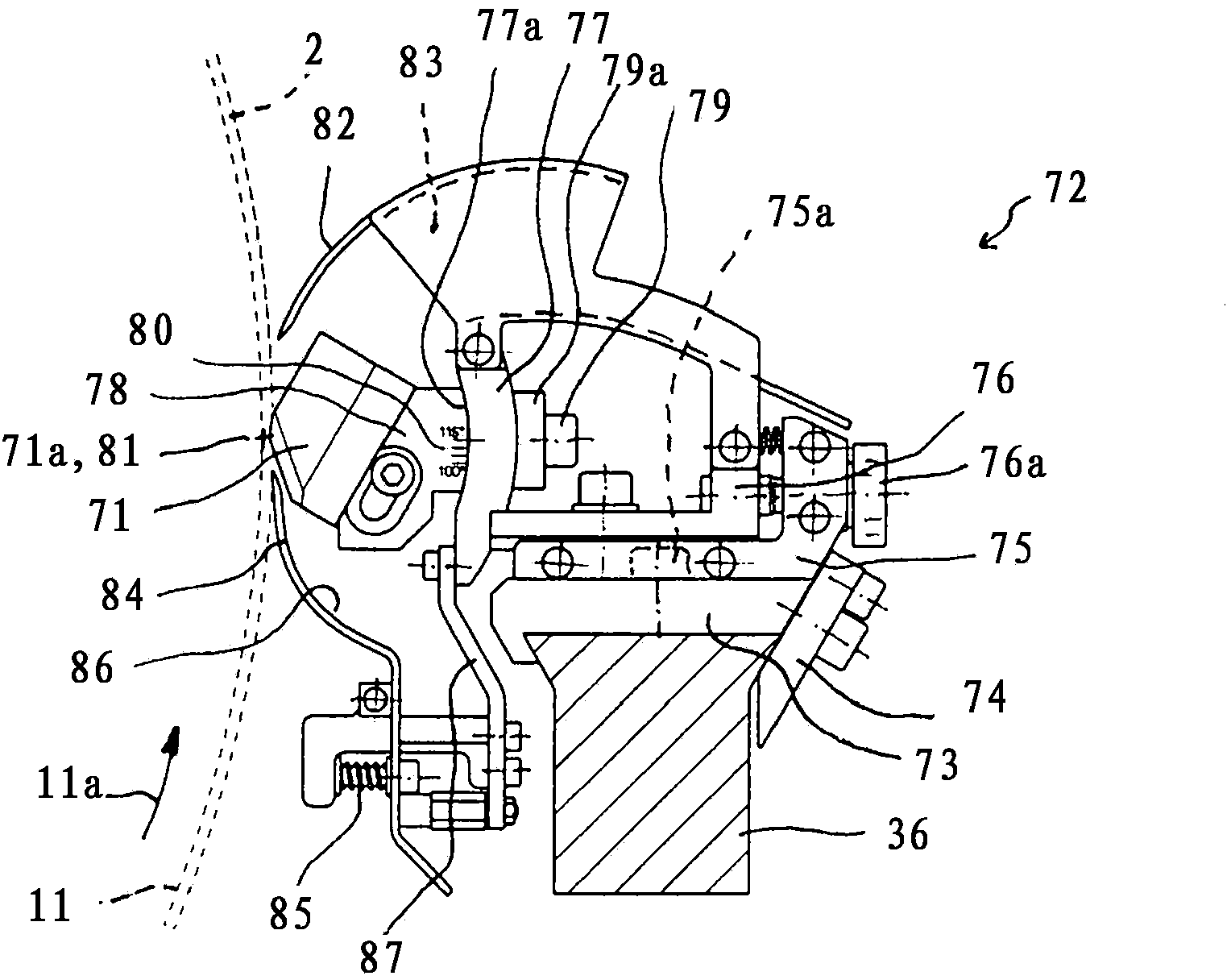
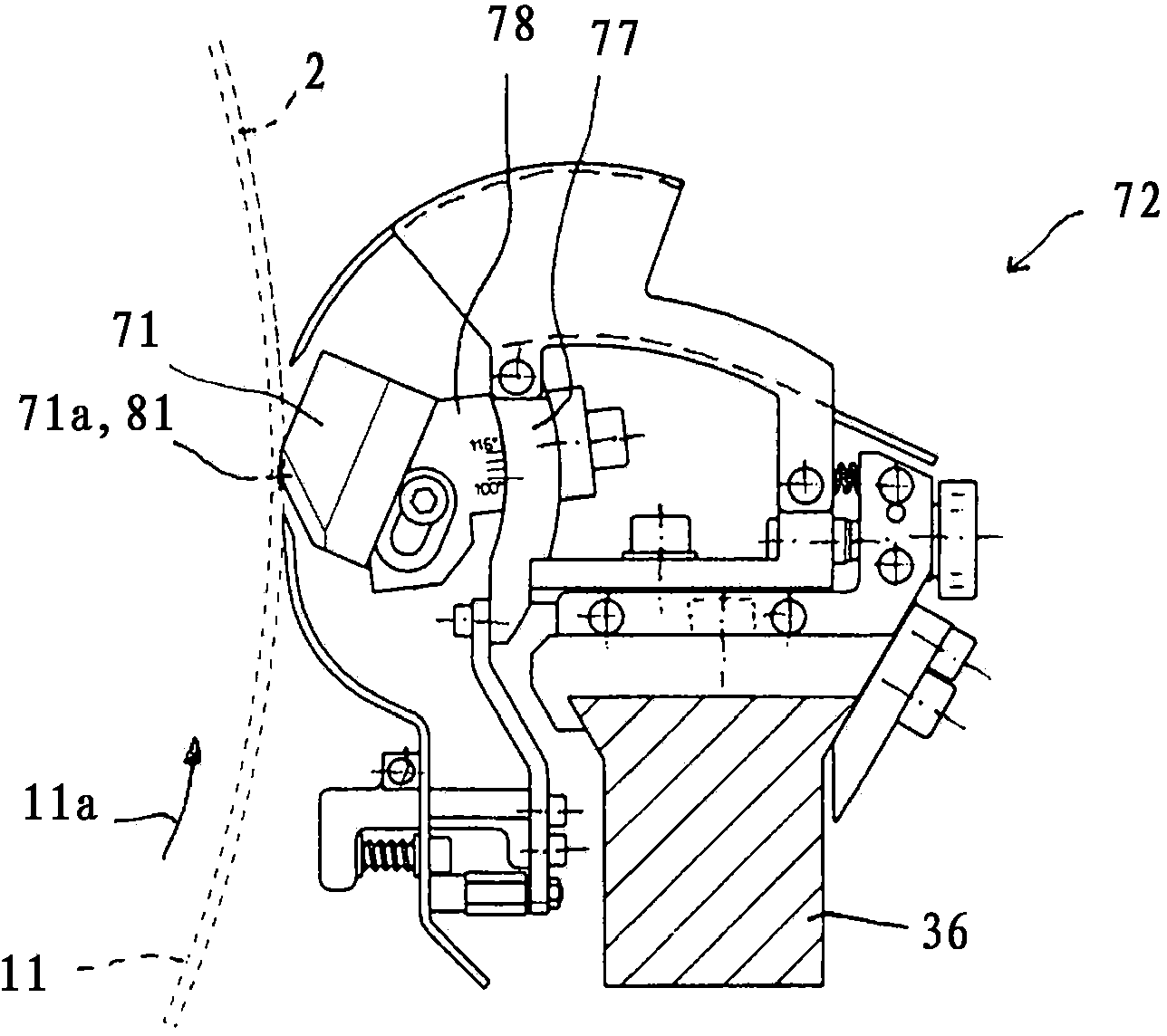
[0023] figure 1 The schematically shown grooving plant 1 basically comprises a driven, horizontally supported transport roller 11 and a plurality of rollers which run continuously around the roller 54 and are spaced apart from each other, forming the inlet 14 and the outlet 15. Belts 51 partially wound around the transport roller 11 and grooving knives 72 arranged between the belts 51 at a defined distance from the drum shell. The cardboard blank 2 conveyed by the conveying device 101 to the inlet 14 is pressed onto the roller shell by the belt 51 in an efficient conveyance (foerderwirksam) and is conveyed along the conveying direction 11a from the inlet 14 at the lower apex of the conveying roller 11 on the conveying roller 11 rotated by approximately 180° to the outlet 15 at the upper apex and is guided there past the grooving knife 72, where a correspondingly designed grooving knife 71 is cut out of the cardboard blank 2 with, for example, a substantially triangular cross-s...


PUM


Abstract

The groove forming device (1) has the rollers (54) that are circulated with an endless belt (51) and spaced to each other. An inlet (14) and an outlet (15) are partially formed on the transport drum (11), and the cardboard blanks (2) are effectively conveyed to the drum. The grooves cutting tool (72) is positioned on the circumference of the drum and provided with a knife receptacle for securing a knife. A sheet guide in the knife receptacle in the grooves cutting tool is adjusted. The center of curvature of the sheet guide is laid in the region of the drum casing.

Description

technical field [0001] The invention relates to a device for slotting cardboard blanks according to the preamble of claim 1 . Background technique [0002] In order to prepare the bends and in particular the sharp-edged beading on the box, triangular grooves are cut into the cardboard blank. The opening angle between the two groove side walls, also referred to as the groove angle, depends on the thickness of the cardboard, the material of the cardboard and the possible one-sided or double-sided covering (Bezug) and on the basis of the cut grooves made of the cardboard blank. Made to determine the features on the box. [0003] A cardboard slotting machine of this type is known from CN 101200091 B. The grooving tool is axially adjustable and installed on the supporting beam arranged parallel to the conveying roller. The grooving tools each have two blades which are fixed at a fixed angle and are inclined to one another on the tool holder. Changing the groove angle is accom...

Claims


Application Information

Patent Timeline
IPC IPC(8): B31B1/22B26D3/08B31B1/14B31B3/14B31B50/22B31B50/25
CPCB26D3/10B26D5/086B26D5/12B26D2007/0043B31B50/25Y10T83/0304B26D3/065
Inventor K·格克G·林特尔曼L·乌格雷特斯
Owner KOLBUS
Why Eureka
Try Eureka