
Method for inspecting the surface of a roll cylinder and device therefor

a technology of rolling cylinder and surface inspection, which is applied in the direction of measuring devices, mechanical measuring arrangements, instruments, etc., can solve the problems of requiring intermediate inspections, deteriorating surface of working rolls, and a large amount of tim

Inactive Publication Date: 2006-02-28
CENT DE RECH METALLURGIQUES CENT VOOR RES IN DE METALLURGIE
View PDF12 Cites 0 Cited by
  • Summary
  • Abstract
  • Description
  • Claims
  • Application Information

AI Technical Summary

Benefits of technology

"The present invention proposes a process for improving the inspection of the surface of a mill roll by adjusting the orientation of the optical axis of the inspection device in relation to the diameter of the roll. This allows for a specular inspection over the entire range of variation in the roll diameter, which occurs several times a day when the roll is in use. The process involves capturing images of the roll surface, analyzing them, and adjusting the optical axis to reduce any differences between the captured images and a reference image. The orientation of the optical axis can be adjusted by mechanical or optical means, and the process can be automated or performed manually. The invention aims to provide a more efficient and effective inspection process for mill rolls."

Problems solved by technology

In the course of rolling, in fact, the surface of the working rolls progressively deteriorates due to oxidation, incrustation of oxide particles, cracking caused by thermal shocks or indeed tearing of metal films under the effect of superficial stresses.
In certain cases, intermediate inspections were required, owing to the presence of defects in the rolled strips for example.
These intermediate unscheduled stops take a lot of time and entail a loss of productivity.
Apart from this disadvantage, the subjective nature of such visual inspections can affect the quality of the examination, which consequently no longer meets current requirements of reliability, reproducibility and rapidity.
Generally speaking, however, the known systems have the disadvantage of inspecting the surface in a fixed direction.

Method used


Image

  • Method for inspecting the surface of a roll cylinder and device therefor
  • Method for inspecting the surface of a roll cylinder and device therefor
  • Method for inspecting the surface of a roll cylinder and device therefor

Examples


Embodiment Construction

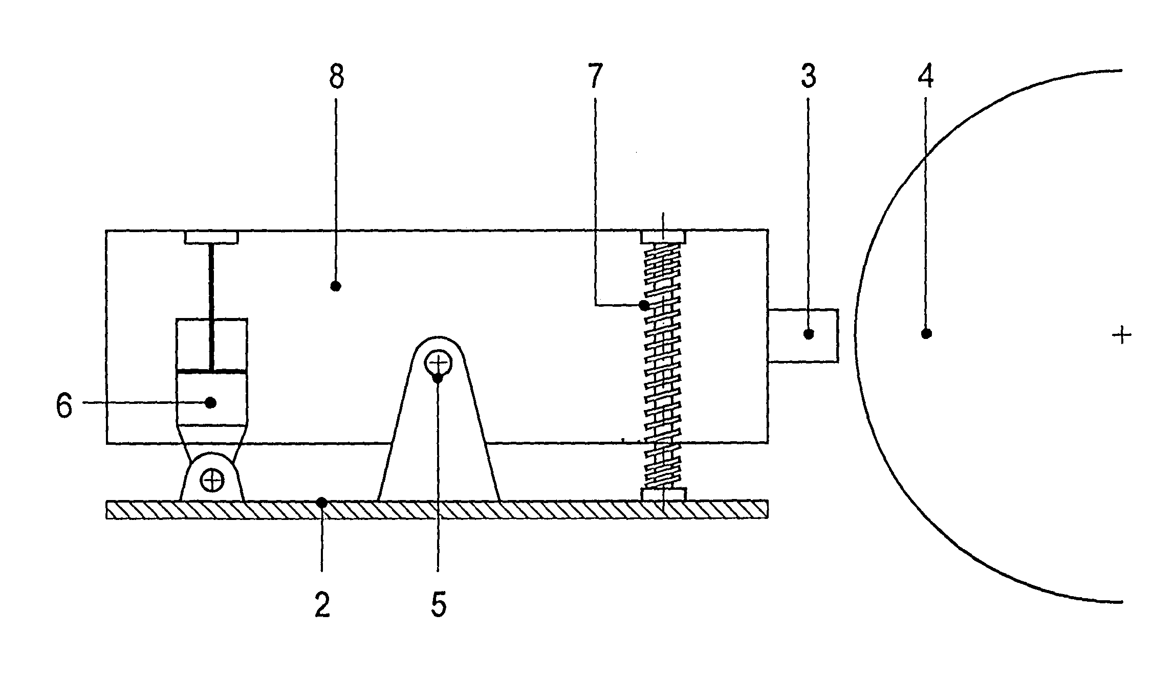
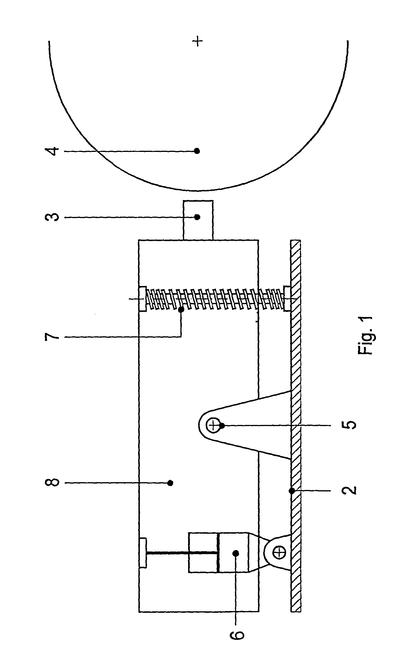
[0051]A mechanical device for adjusting the inclination of the optical axis of an inspection device has been diagrammatically represented in FIG. 1.

[0052]The inspection device, represented here taken as a whole by the protection housing 8, is mounted on a fixed support 2 forming part of a rolling mill stand. Its aiming cap 3 is directed towards a mill roll 4; this is, for example, a lower roll of a hot-rolling finishing stand.

[0053]In this embodiment, the inspection device is mounted on the fixed support 2 by way of bearings 5, only one of which is visible in the figure, in such a way as to be able to pivot about an axis parallel to the axis of the roll 4. The pivoting movement of the inspection device is applied by means of a pneumatic cylinder 6 arranged between the fixed support 2 and the inspection device 1, for example. A spring 7 arranged on the far side of the articulation 5 in relation to the cylinder 6 allows to damp the pivoting movement of the inspection device.

[0054]A di...


PUM

PropertyMeasurementUnit
diameteraaaaaaaaaa
sizeaaaaaaaaaa
gravityaaaaaaaaaa

Abstract

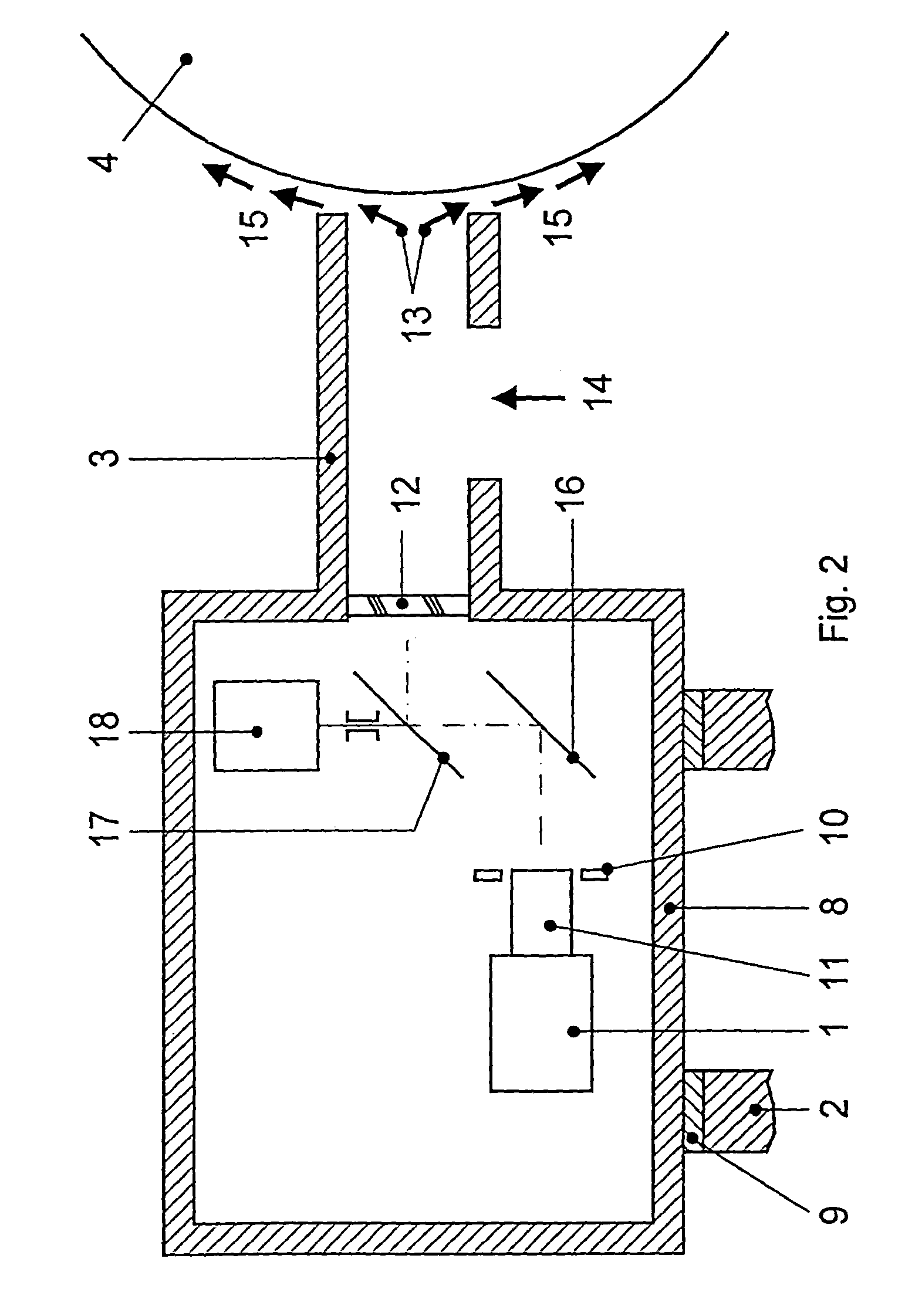
In a process for the inspection of the surface of a cylindrical body and more especially that of a mill roll, at least one zone of the surface is observed by means of an inspection device having an optical axis oriented towards this zone of the surface with a view to determining the state of the surface. To this end, at least one image of the zone supplied by the inspection device is captured, at least one of the images captured is analysed, the analysis of the image or images captured is compared with the analysis of a reference image, the differences between the analysis of the image or images captured and the analysis of the reference image are detected, and at least the orientation of the optical axis is adjusted so as at least to reduce and preferably to eliminate the differences found.The device can include mechanical and / or optical means of adjusting the orientation of the optical axis.

Description

[0001]This is a nationalization of PCT / BE02 / 00060 filed Apr. 23, 2002 and published in French.BACKGROUND OF THE INVENTION[0002]1. Field of the Invention[0003]The present invention concerns a process for the inspection of the surface of a mill roll, and more generally of a cylindrical body. It likewise relates to a device for implementing this process.[0004]2. Description of the Related Art[0005]There are numerous applications in the industry in which the condition of the surface of a manufacturing tool at least partially determines the quality of the manufactured product. One extremely important particular instance is that of the manufacture of steel strips, the surface finish of which depends to a large extend on the condition of the surface of the working rolls of the rolling mill.[0006]In the course of rolling, in fact, the surface of the working rolls progressively deteriorates due to oxidation, incrustation of oxide particles, cracking caused by thermal shocks or indeed tearing...

Claims


Application Information

Patent Timeline
Patent Type & Authority Patents(United States)
IPC IPC(8): G01N21/00B21B28/02G01B21/20G01V8/00G01N21/892B21B28/00B21B38/00B21C51/00G01N21/952
CPCB21B38/00G01N21/952B21B2267/10G01B11/00
Inventor FRANSSEN, ROGERSCHYNS, MARCUIJTDEBROEKS, HUGO
Owner CENT DE RECH METALLURGIQUES CENT VOOR RES IN DE METALLURGIE
Learn More