Quick connector coupler

A connector, fast technology, applied in the direction of coupling, mechanical equipment, etc., can solve the problems of large volume, difficult to assemble, complex design and so on

Active Publication Date: 2014-05-21
TI AUTOMOTIVE FULDABRUCK
View PDF6 Cites 24 Cited by
  • Summary
  • Abstract
  • Description
  • Claims
  • Application Information

AI Technical Summary

Problems solved by technology

The quick connector joints known in practice have the disadvantage that their design is complex; they are difficult to assemble and have a large volume
This makes it partly difficult to use the known quick connector joints in the hard-to-reach or tight spaces of motor vehicles

Method used


Image

  • Quick connector coupler
  • Quick connector coupler
  • Quick connector coupler

Examples


Embodiment Construction

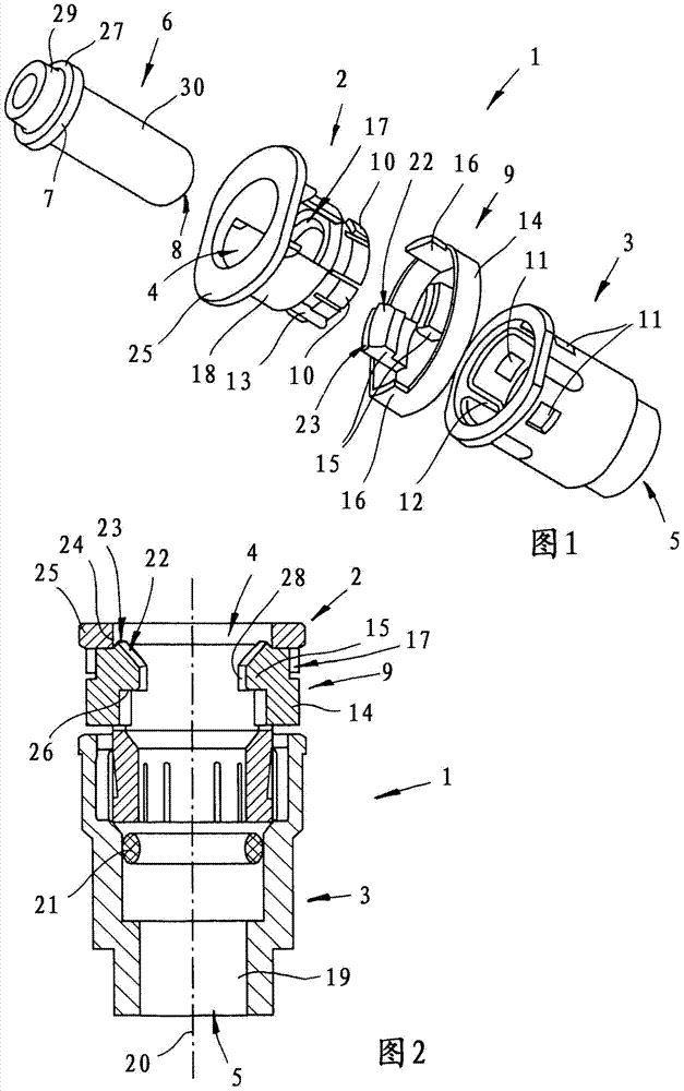
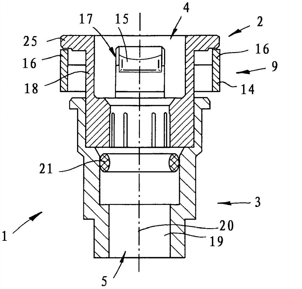
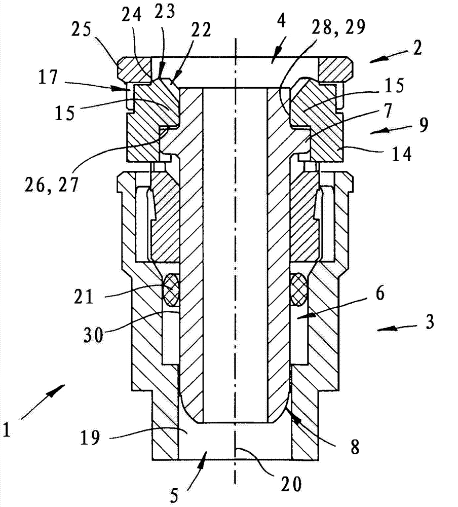
[0060] exist figure 1 , a quick connector fitting 1 is shown comprising a substantially cylindrical hollow body comprising a head element 2 connected to a sealing element 3 . These elements are along the Figures 2 to 4 The shown longitudinal axis 20 defines the through bore 19 . The head element 2 comprises at one end a male member inlet port 4 formed by a cylindrical surface 24 in a cover 25 at the end of the head element 2 . The opposite end comprises an insert portion comprising a wall 80 with a slot in the axial direction. according to figure 1 , the sealing element 3 comprises an outlet port 5 at the end axially furthest from the head element 2 . As shown, the end of the sealing element 3 defining the outlet port 5 is configured to define a barbed hose connection aligned along the longitudinal axis 20 . As is common in quick connector constructions, the barbed hose connection end of the connector body may be disposed at an angle, such as at a ninety degree (90°) ang...


PUM


Abstract

The invention relates to a quick connector coupler, which comprises a connector body to receive a male member with a radial upset comprised of two separate, interconnected components, a head element and a sealing element which define a through-hole from a male member entry port at the end of the head element axially to an exit port at the end of the sealing element. A retainer for releasably securing the male member to the connector body is ring-shaped, and encircles the connector body head element. It includes at least one retainer element, which reaches through a window in the head element and interacts with the radial upset of the male member to secure the male member in the connector body.

Description

technical field [0001] The present invention relates to quick connector fittings for forming separable connections in fluid lines. Background technique [0002] Quick connector fittings of the type described above are well known in actual practice. These quick connector fittings are used, for example, in fluid line systems in motor vehicles and must form a fluid-impermeable reliable connection between two lines for extended periods of time under variable external conditions. These quick connector fittings known from practice have the disadvantage that their design is complex; they are difficult to assemble and have a large volume. This makes it partly difficult to use known quick connector fittings in practice in hard-to-reach or tight spaces of motor vehicles. Contents of the invention [0003] The challenge faced by the present invention is therefore to provide a quick connector fitting which is characterized by simple assembly, compact design and high functional safet...

Claims


Application Information

Patent Timeline
Patent Type & Authority Applications(China)
IPC IPC(8): F16L37/08
CPCF16L37/084F16L37/0985F16L37/252
Inventor I·巴特尔A·博尔K·布比H·延森R·佩珀
Owner TI AUTOMOTIVE FULDABRUCK
Why Eureka
Try Eureka