Lubrication device with automatic oil filling capacity

A lubricating device and automatic oil replenishment technology, which is applied in the direction of engine lubrication, lubricating parts, and lubricating oil input, can solve problems such as time waste, reduce the number of parts, improve equipment utilization, and save oil replenishment time Effect

Active Publication Date: 2014-05-21
ZHEJIANG GEELY HOLDING (GROUP) CO LTD +1
View PDF6 Cites 11 Cited by
  • Summary
  • Abstract
  • Description
  • Claims
  • Application Information

AI Technical Summary

Problems solved by technology

[0003] The invention provides a lubricating device that can automatically add lubricating oil to the lubricating oil tank and can automatically replenish oil, which solves the problem of wasting time caused by manually adding lubricating oil to the lubricating oil tank in the existing lubricating device

Method used


Image

  • Lubrication device with automatic oil filling capacity
  • Lubrication device with automatic oil filling capacity
  • Lubrication device with automatic oil filling capacity

Examples


Embodiment 1

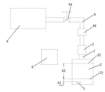
[0024] Embodiment one, see figure 1 , a lubricating device that can automatically replenish oil, including a lubricating oil tank 2, a main oil tank 4 and a control unit 6. An oil quantity sensor 7 is installed in the lubricating oil tank 2 . The fuel quantity sensor 7 is a pressure sensor. The oil quantity sensor 7 and the control unit 6 are electrically connected together. Lubricating oil tank 2 is provided with oil pipe interface 1. The oil pipe interface 1 is located at the upper end of the lubricating oil tank 2 . The main oil tank 4 is located above the lubricating oil tank 2 . The outlet of the main oil tank 4 is provided with an oil pipe 5 . Oil pipe 5 and main oil tank 5 are connected together by flexible pipe. Oil pipe 5 and oil pipe interface 1 are butted together. A sealing ring is arranged between the oil pipe 5 and the oil pipe interface 1 . Oil pipe 5 and oil pipe interface 1 are fixed together by connecting nut 3 . The oil pipe 5 is provided with a man...

Embodiment 2

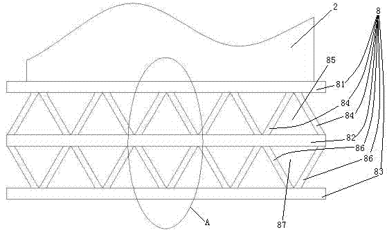
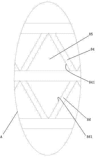
[0026] Embodiment two, see figure 2 , the difference with the first embodiment is: a mounting frame 8 is also provided. The mounting frame 8 includes an upper base plate 81 , a middle base plate 82 and a lower base plate 83 distributed along the vertical direction. A number of inclined support plates 84 are provided between the upper base plate 81 and the middle base plate 82 . Several upper deformation channels 85 extending along the horizontal direction are enclosed between the upper base plate 81 , the middle base plate 82 and the upper inclined support plate 84 . The upper deformation channel 85 is triangular. Between the lower base plate 83 and the middle base plate 82 are provided several downwardly inclined support plates 86 . A plurality of lower deformation channels 87 extending along the horizontal direction are enclosed between the lower base plate 83 , the middle base plate 82 and the lower inclined support plate 86 . The lower deformation channel 87 is triang...

Embodiment 3

[0029] Embodiment three, see Figure 4 , The difference with the second embodiment is: the two ends of the upper deformation channel 85 and the lower deformation channel 87 are provided with end caps 80, so that the upper deformation channel 85 and the lower deformation channel 87 form a closed cavity. The upper inclined support plate between the adjacent upper deformation channels 85 in the upper inclined support plate 84, the lower inclined support plate between the adjacent lower deformation channels 87 in the lower inclined support plate 86, and the middle base plate 82 are located on the corresponding A damping channel 88 is provided at the position between the adjacent upper deformation channel and the lower deformation channel. Both the upper deformation channel 85 and the lower deformation channel 87 are filled with damping fluid (the damping fluid is not shown in the figure). The upper deformation channel 85 and the lower deformation channel 87 are provided with an e...


PUM


Abstract

The invention relates to a lubrication device with automatic oil filling capacity. The lubrication device comprises a lubrication oil tank, a main oil tank and a control unit, wherein the main oil tank is located above the lubrication oil tank which is connected with the main oil tank through an oil pipe provided with an electrically operated valve, and the lubrication oil tank is provided with an oil sensor; and the control unit is used for switching on the electrically operated valve so as to enable lubricating oil in the main oil tank to flow into the lubrication oil tank under the action of gravity when the oil sensor detects that oil in the lubrication oil tank is less than the set minimum quantity and switching off the electrically operated valve when the oil in the lubrication oil tank reaches the set maximum quantity. The lubrication device with the automatic oil filling capacity can fill the lubrication oil tank automatically with the lubrication oil, so that the problem of time waste caused by the fact that the conventional lubrication device requires manual lubrication oil filling into the lubrication oil tank is solved.

Description

technical field [0001] The invention relates to a lubricating device, in particular to a lubricating device capable of automatically replenishing oil. Background technique [0002] In mechanical equipment such as machine tools, a lubrication system is usually provided to lubricate the moving parts of the equipment. A lubricating device is disclosed in Chinese patent No. 2013202443895 and a patent document titled "Automatic Lubricating Device for CNC Machine Tool". Existing lubricating devices all include a lubricating oil tank and a lubricating oil delivery structure that delivers the lubricating oil in the lubricating oil tank to the parts that require lubrication as disclosed in this patent. However, the existing press manually adds lubricating oil to the lubricating oil tank, and the press needs to add lubricating oil once every 120 minutes of operation on average. Need 2 people to fill, time-consuming 10 minutes, with working 8 hours every day, then can cause t...

Claims


Application Information

Patent Timeline
Patent Type & Authority Applications(China)
IPC IPC(8): F16N37/00B23Q11/12
Inventor 郭华侯毅侯海靖
Owner ZHEJIANG GEELY HOLDING (GROUP) CO LTD
Why Eureka
Try Eureka