Stage lamp optical system with mutually-switched pattern and light beam effect

A light optics and light beam technology, applied in the field of stage lighting optics system, can solve problems such as poor practicability, poor light effect, and large loss of pattern effect light, and achieve the effect of improving utilization efficiency and fast switching

Active Publication Date: 2014-05-21
GUANGZHOU HAOYANG ELECTRONICS CO LTD
View PDF1 Cites 8 Cited by
  • Summary
  • Abstract
  • Description
  • Claims
  • Application Information

AI Technical Summary

Problems solved by technology

However, homogenization and light beam are two kinds of luminous effects with great difference. The former is to diverge the light, and the latter is to concentrate the light. For the structure of the above patent, the first optical component is located between the light source and the second optical component. Adding directly requires enough space to be reserved, which brings certain disadvantages to the selection of the light source. The position between the light source and the second optical component is relatively short, and the practicability is relatively poor; in addition, when the beam effect is converted to For the pattern effect, when the optical components are cut into the position of the main optical axis, the optimal parameters of the optical position of the optical components such as the light guide or the light guide and the lens assembly are not considered, resulting in a large loss of light in the final pattern effect light. Light effect difference

Method used


Image

  • Stage lamp optical system with mutually-switched pattern and light beam effect
  • Stage lamp optical system with mutually-switched pattern and light beam effect

Examples


Embodiment Construction

[0018] The present invention will be further described below in conjunction with specific examples.

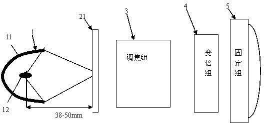
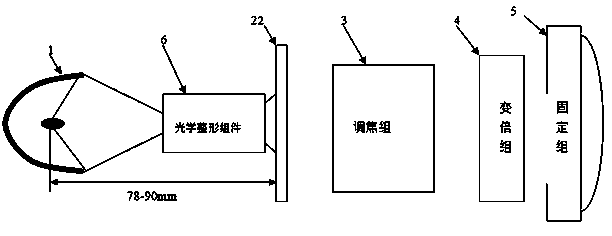
[0019] Such as figure 1 As shown, the present invention discloses a stage light optical system with mutual switching between patterns and beam effects, which includes a light source assembly 1 capable of emitting concentrated light, a pattern assembly and a zoom lens assembly located in the same main optical axis direction, wherein the The system also includes an optical integrator assembly 6 that can be switched into the main optical axis. The pattern assembly includes a light beam pattern assembly 21 and a pattern pattern assembly 22 that can be switched mutually and enter the main optical axis. The optical axis moves back and forth relative to the pattern component. When the light source component 1 moves forward relative to the pattern component to the first position, only the light beam pattern component 21 switches into the main optical axis, and the light of the light s...


PUM

PropertyMeasurementUnit
The inside diameter ofaaaaaaaaaa

Abstract

The invention relates to a stage lamp optical system with a mutually-switched pattern and light beam effect. The stage lamp optical system comprises a light source component, a pattern component and a zoom lens component which are positioned in the same main optical axis direction and can emit spot light, and also comprises an optical integrator component which can be switched into the main optical axis, wherein the pattern component comprises a light beam pattern component and a graph pattern component which can switch mutually and enter the main optical axis; the light source component can move forward and backward relative to the pattern component along the main optical axis; when the light source component is moved forward to the first position relative to the pattern component, only the light beam pattern component is switched into the main optical axis; the light rays of the light source component are emitted through the light beam pattern component and the zoom lens component; when the light source component is moved backward to the second position relative to the pattern component, the optical integrator component and the graph pattern component enter the main optical shaft at the same time, and the light rays are emitted through the optical integrator component, the graph pattern component and the zoom lens component. The stage lamp optical system with the mutually switched patterns and light beams has the advantages of low optical loss, high utilization rate and the like.

Description

technical field [0001] The invention relates to a stage lighting optical system for switching patterns and beam effects. Background technique [0002] At present, the most widely used functional lamps in the field of stage lights mainly include three types: pattern lights, beam lights, and soft lights. Stage designers and users often choose different functional lamps in a targeted manner according to the needs of use. However, due to the use of a single, complex stage scene, it is necessary to replace and use different types of lamps and lanterns, which is extremely complicated to operate. In order to solve this problem, stage lamps for realizing various light beam effects are also proposed in the prior art. [0003] Chinese patent CN201320192500.0 discloses a stage lighting system including multiple beam effects at the same time, which includes a light source, a reflective bowl, an optical component 1, and an optical component 2; the optical component 1 is located bet...

Claims


Application Information

Patent Timeline
IPC IPC(8): F21S8/00F21V7/00F21V14/00F21W131/105
CPCF21V14/02F21S10/00F21W2131/105F21W2131/406G03B21/00
Inventor 蒋伟楷
Owner GUANGZHOU HAOYANG ELECTRONICS CO LTD
Why Eureka
Try Eureka