
Resonance and standing wave dual-purpose demonstrator

A demonstrator and standing wave technology, applied in the field of both resonance and standing wave demonstrators, can solve the problems that standing waves cannot be observed from a distance, single, only 50HZ standing wave phenomenon, and the experimental process is boring.

Inactive Publication Date: 2014-05-21
江苏省天一中学
View PDF0 Cites 2 Cited by
  • Summary
  • Abstract
  • Description
  • Claims
  • Application Information

AI Technical Summary

Problems solved by technology

[0002] In middle school physics teaching, the resonance in the mechanical vibration and the standing wave of the rope wave have always been the focus and difficulty. In the traditional experiment, the frequency and amplitude of the driving force are not adjustable, which makes the phenomenon in the experiment demonstration process not ideal. The experimental process is tedious, which limits the experimental display
For example, in the resonance experiment of mechanical vibration before, the resonance pendulum experimental device was used to demonstrate that when the natural vibration frequencies of the two white balls are the same, a resonance phenomenon occurs between the two pendulum balls, but because the frequency and amplitude of the driving force cannot Adjustment, so that the swing of the white ball is not obvious, and the resonance phenomenon cannot be accurately understood according to the phenomenon; when doing the standing wave experiment of the soft rope, the traditional method is to use a dot counter to assemble a standing wave device to demonstrate the standing wave phenomenon, but this device has Two disadvantages, first, the vibration amplitude is relatively small, and the standing wave generated cannot be observed at a long distance; second, the frequency is single, and the standing wave phenomenon of 50HZ can only be observed. Accurate and intuitive observation, so it is difficult to understand the standing wave phenomenon visually

Method used


Image

  • Resonance and standing wave dual-purpose demonstrator
  • Resonance and standing wave dual-purpose demonstrator

Examples


Embodiment Construction

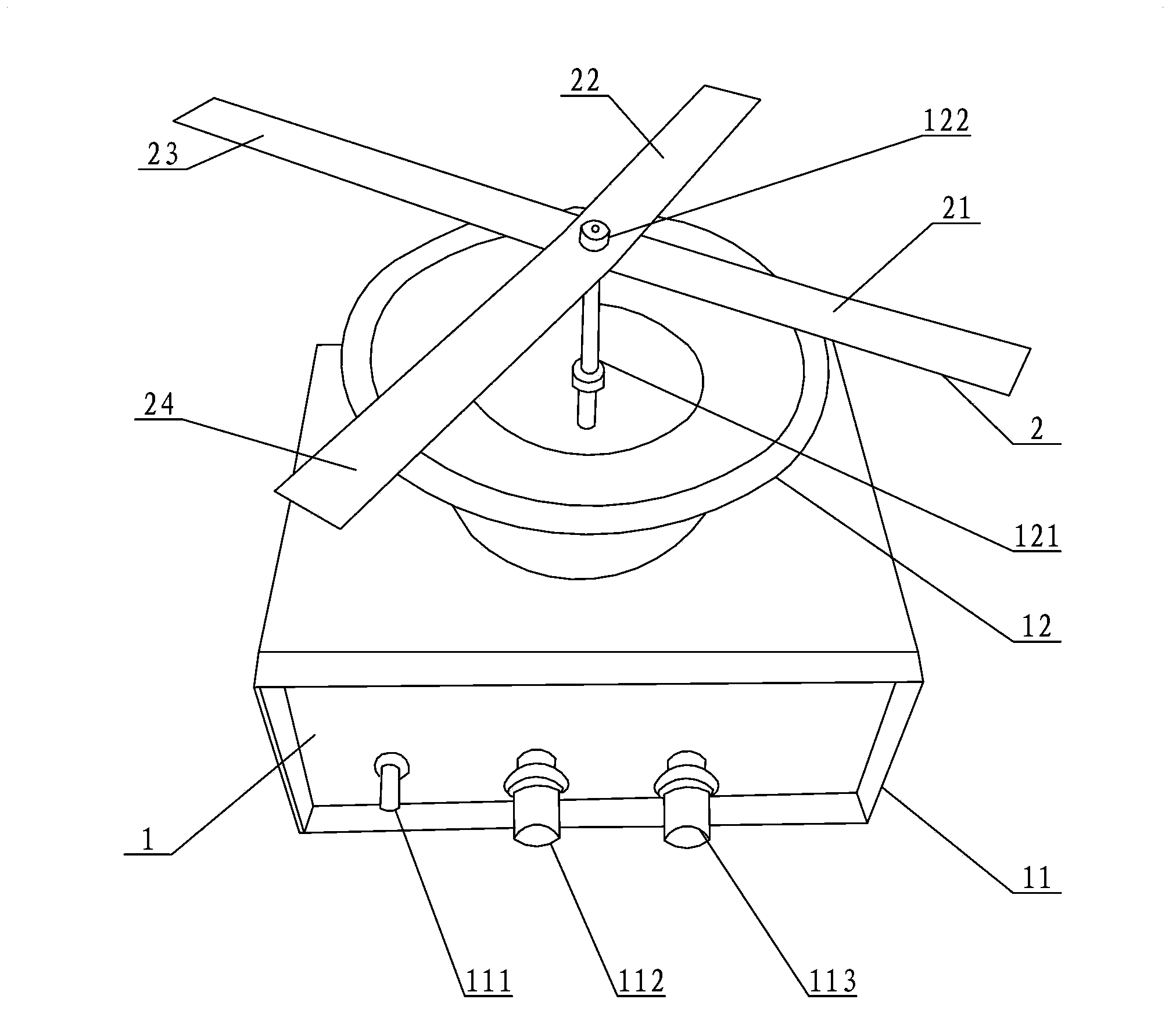
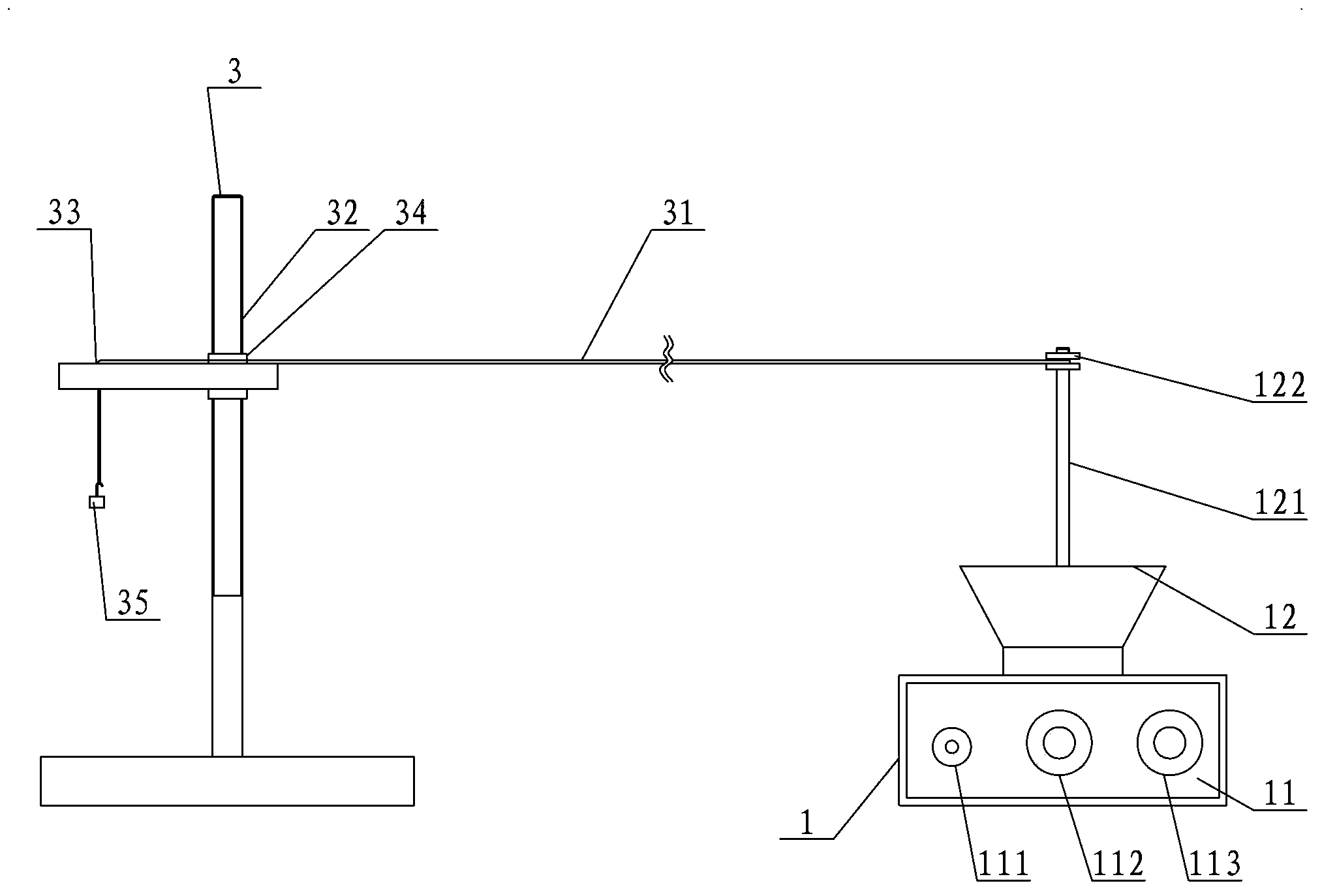
[0016] Such as Figure 1~2 In the shown embodiment, the resonance and standing wave dual-purpose demonstrator of the present invention includes a generator 1, a mechanical vibrating piece 2 and a standing wave demonstration auxiliary device 3, and the generator 1 includes a sine wave signal generator 11 and a mechanical vibration Generator 12, a power switch 111, a frequency adjustment knob 112 and an amplitude adjustment knob 113 are arranged on the casing of the sine wave signal generator 11. The sine wave signal generator 11 also includes a signal amplification circuit, and the input terminal of the signal amplification circuit is electrically connected to the frequency adjustment Knob 112 and amplitude adjustment knob 113, the output end of the signal amplification circuit is electrically connected to the mechanical vibration generator 12, the mechanical vibration generator 12 includes a fixed rod 121 provided at its center, the fixed rod 121 is provided with threads, and t...


PUM


Abstract

The invention discloses a resonance and standing wave dual-purpose demonstrator comprising a generator, mechanical vibration sheets, and a standing wave demonstration auxiliary device. The generator comprises a sine wave signal generator and a mechanical vibration generator. A power switch, a frequency adjusting knob, and an amplitude adjusting knob are disposed on the sine wave signal generator. The sine wave signal generator also comprises a signal amplification circuit. The input end of the signal amplification circuit is electrically connected with the frequency adjusting knob and the amplitude adjusting knob. The output end of the signal amplification circuit is electrically connected with mechanical vibration generator. The mechanical vibration generator comprises a fixing rod disposed on the centre of the mechanical vibration generator. By providing the sine wave signal generator with adjustable frequency and amplitude, a changeable electric signal can be connected with the mechanical vibration generator so as to generate different sine mechanical vibrations which are successively represented by vibration sheets, with different intrinsic frequencies, disposed on the mechanical vibration generator. Standing wave phenomena with different wave loops and wave nodes are observed via a flexible rope on the standing wave demonstration auxiliary device.

Description

technical field [0001] The invention relates to the technical field of physical mechanical wave theory demonstration experiments, in particular to a dual-purpose demonstrator for resonance and standing waves. Background technique [0002] In middle school physics teaching, the resonance in the mechanical vibration and the standing wave of the rope wave have always been the focus and difficulty. In the traditional experiment, the frequency and amplitude of the driving force are not adjustable, which makes the phenomenon in the experiment demonstration process not ideal. The experimental process is relatively tedious, which limits the experimental display. For example, in the resonance experiment of mechanical vibration before, the resonance pendulum experimental device was used to demonstrate that when the natural vibration frequencies of the two white balls are the same, a resonance phenomenon occurs between the two pendulum balls, but because the frequency and amplitude of ...

Claims


Application Information

Patent Timeline
Patent Type & Authority Applications(China)
IPC IPC(8): G09B23/10
Inventor 杨懿邓一波蒋建明
Owner 江苏省天一中学
Learn More