Brake controller for vehicle

A technology of braking device and control device, applied in the direction of braking control system, brake, braking components, etc., can solve the problems of heavy load of friction brake and increase cost, and achieve the goal of improving reliability, avoiding cost and reducing test difficulty. Effect

Active Publication Date: 2014-05-21
BOMBARDIER TRANSPORTATION GMBH
View PDF8 Cites 8 Cited by
  • Summary
  • Abstract
  • Description
  • Claims
  • Application Information

AI Technical Summary

Problems solved by technology

In this case, however, all friction brakes of the vehicle are subject to a stronger load
Additionally, this approach requires the use of multiple independent friction braking systems, increasing the cost of the vehicle

Method used


Image

  • Brake controller for vehicle
  • Brake controller for vehicle

Examples


Embodiment Construction

[0034] Further preferred embodiments of the invention are explained in the subclaims and the following description of preferred embodiments in conjunction with the drawings.

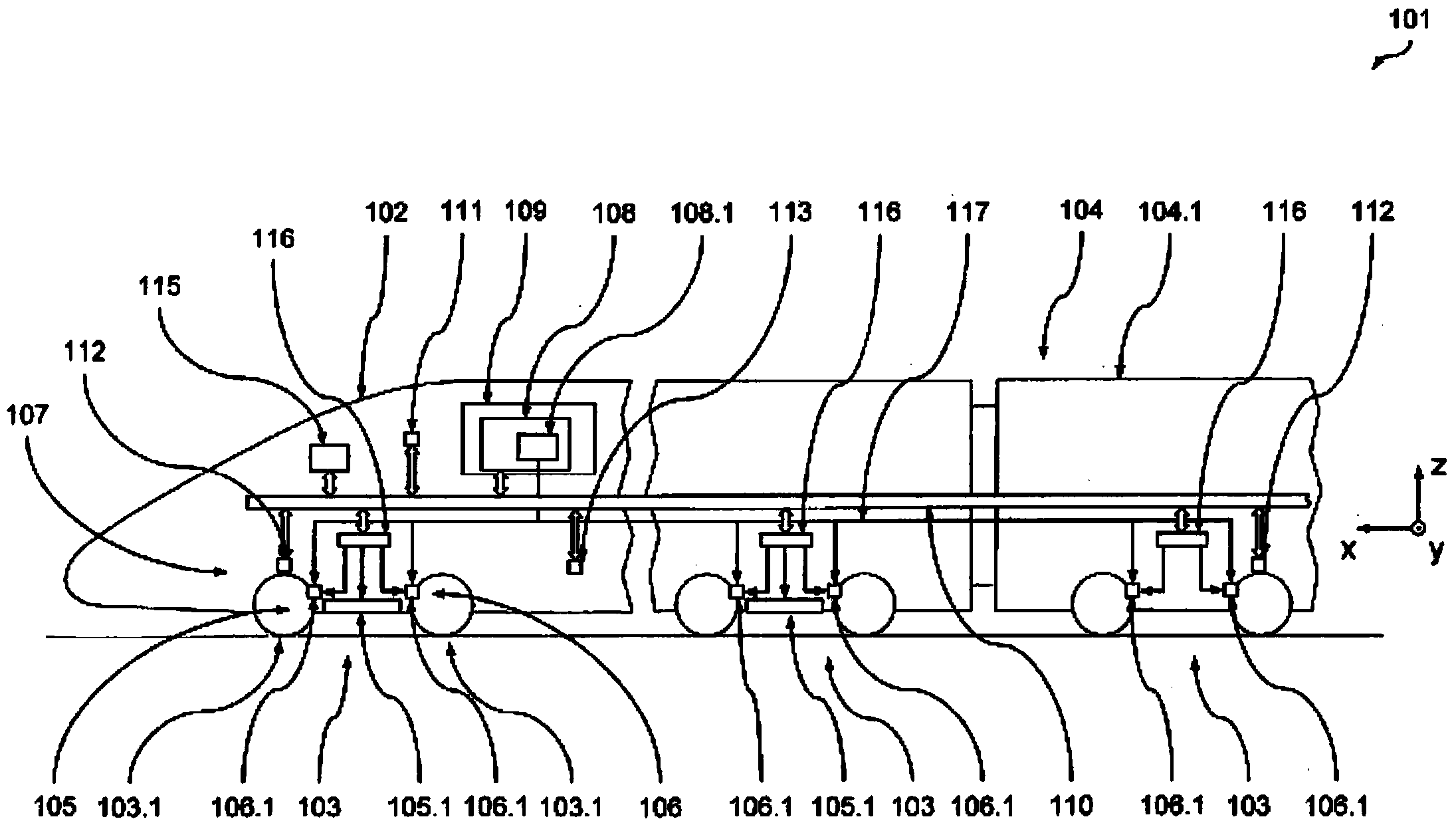
[0035] Refer below figure 1 and 2 A preferred embodiment of the rail vehicle 101 of the present invention will be described. The rail vehicle 101 is a train used for high-speed traffic, and its rated operating speed is greater than 250 km / h, namely V n =300 km / h to 380 km / h.

[0036] The vehicle 101 comprises a nose 102 , the end regions of which body 102 . 1 is supported in conventional manner on a chassis in the form of a vehicle bogie 103 . However, the invention can also be used in conjunction with other arrangements in which the body is supported only on a chassis. A further central carriage 104 is connected to the front, whose body 104 . 1 is likewise supported on the vehicle bogie 103 .

[0037] In order to make the following description easy to understand, the figure 1 The vehicle coordinat...


PUM


Abstract

The present invention relates to a method for activating a brake device of a vehicle, in particular of a rail vehicle for high-speed operation, in which, in a determination step, at least one actual deceleration signal which is representative of a current actual decleration of the vehicle (101) in a longitudinal direction of a vehicle and is independent of an operating state of the brake device (107) of the vehicle (101) is determined and, in a comparison step, the actual deceleration signal is compared with a predeterminable desired decleration signal, wherein the desired deceleration signal is representative of a currently predetermined desired deceleration of the vehicle (101), and, in an actuating step, at least one brake unit (105, 106) of the brake device (107) is activated depending on the result of the comparison step in order to assist a braking action of the brake device (107). The actual deceleration signal is determined in the determination step using a plurality of component signals which are independent of one another, wherein each component signal is representative of the current actual deceleration of the vehicle (101) in the longitudinal direction of the vehicle.

Description

technical field [0001] The invention relates to a braking method for controlling a vehicle, in particular a high-speed rail vehicle, in which at least one is determined in a determination step representative of the current actual deceleration of the vehicle in the longitudinal direction of the vehicle, and an actual deceleration signal independent of the operating state of the brake system of the vehicle, which is compared in a comparison step with a prespecifiable setpoint deceleration signal, wherein the setpoint deceleration signal representative for the current pre-specified nominal deceleration of the vehicle, and in an actuating step, based on the result of said comparing step, at least one braking unit of said braking device is controlled to support said braking The braking effect of the device. The invention also relates to a device and a vehicle for implementing such a method. Background technique [0002] For vehicles, especially modern rail vehicles running at a...

Claims


Application Information

Patent Timeline
Patent Type & Authority Applications(China)
IPC IPC(8): B60T8/17B60T8/172
CPCB60T8/1705B60L2200/26B60T8/172B60T2270/413
Inventor 丹尼尔·弗雷泽格奥尔格·尼什维茨迈克尔·布莱姆克里斯·约翰森
Owner BOMBARDIER TRANSPORTATION GMBH
Why Eureka
Try Eureka