
High-efficiency energy-saving bending machine

A high-efficiency energy-saving bending machine technology, applied in the field of bending devices, can solve problems such as unfavorable production efficiency, cumbersome steps, and complex structure, and achieve the effect of enhancing guiding and supporting functions, reducing cumbersomeness, and increasing the force-bearing area

Active Publication Date: 2014-05-28
江苏九澍机电科技有限公司
View PDF6 Cites 4 Cited by
  • Summary
  • Abstract
  • Description
  • Claims
  • Application Information

AI Technical Summary

Problems solved by technology

[0002] In industrial production and life, metal rods with complex structures are usually used, for example, a new type of metal frame, which is the raw material - metal rods are processed by multiple bending, which includes bending the metal rods Bending into a V shape, and turning the two ends of the V shape outwards to form a curved shape. In the prior art, it is usually divided into two processes and completed separately. The first step is to bend it into a V shape through a set of tooling. Then use another set of tooling to bend its two ends. This method is cumbersome and requires multiple sets of positioning, clamping, and processing devices, which is not conducive to improving production efficiency.

Method used


Image

  • High-efficiency energy-saving bending machine
  • High-efficiency energy-saving bending machine
  • High-efficiency energy-saving bending machine

Examples


Embodiment Construction

[0024] The present invention will be further described below in conjunction with the accompanying drawings.

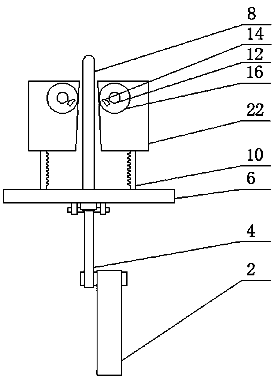
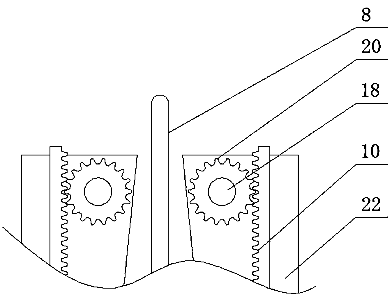
[0025] Figure 1 to Figure 3 It is the first embodiment of the present invention, which includes two horizontal baffles 26 arranged in gaps, behind each baffle 26 there is a turntable 16 driven to rotate by a power device, and the upper surface of the turntable 16 is provided with the turntable 16. The concentric and columnar first bump 14 and the second bump 12 eccentrically arranged on the turntable 16 are fixedly connected to the transmission shaft 18 under the turntable 16, and a fixed plate 22 is also provided under the turntable 16, and the transmission shaft 18 is Through the fixed plate 22 and fixed on the fixed plate 22 by bearings, there are also gears 20 fixedly connected to the two transmission shafts 18 below the fixed plate 22, and the gears 20 are provided with racks 10 meshing with them. A push rod 8 is also arranged between the two rotating disks 16 ....


PUM


Abstract

The invention discloses a high-efficiency energy-saving bending machine, which comprises two horizontal baffles (26) arranged at intervals, wherein a turntable (16) which is driven to rotate by a power unit is arranged behind each baffle (26); the upper surface of each turntable (16) is provided with a first cylindrical lug (14) concentric with the turntable (16) and a second lug (12) eccentrically arranged on the turntable (16); a push rod (18) which is arranged along the symmetry axis of the two turntables (16) is arranged between the two turntables (16). The high-efficiency energy-saving bending machine can bend workpieces twice at the same station, the complicated degree of machining is greatly reduced, and the production efficiency is improved.

Description

technical field [0001] The invention relates to a bending device. Background technique [0002] In industrial production and life, metal rods with complex structures are usually used, for example, a new type of metal frame, which is the raw material-metal rods are processed by multiple bending, which includes bending the metal rods Bending into a V shape, and turning the two ends of the V shape outwards to form a curved shape. In the prior art, it is usually divided into two processes and completed separately. The first step is to bend it into a V shape through a set of tooling. Then use another set of tooling to bend its two ends. This method is cumbersome and requires multiple sets of positioning, clamping, and processing devices, which is not conducive to improving production efficiency. Contents of the invention [0003] The technical problem to be solved by the present invention is to provide a bending device that can reduce the complexity of processing. [0004] In...

Claims


Application Information

Patent Timeline
Patent Type & Authority Applications(China)
IPC IPC(8): B21D7/00
Inventor 曹越
Owner 江苏九澍机电科技有限公司
Learn More