Speed limiter with car slipping preventive device

An anti-slip and speed limiter technology, applied in the directions of transportation, packaging, elevators, etc., can solve problems such as reducing the safety and reliability of elevator operation, and achieve the effect of preventing safety accidents or personal casualties and improving safety and reliability.

Active Publication Date: 2014-05-28
NINGBO OULING ELEVATOR COMPONENTS
View PDF5 Cites 3 Cited by
  • Summary
  • Abstract
  • Description
  • Claims
  • Application Information

AI Technical Summary

Problems solved by technology

[0003] At present, elevators are almost used in high-rise buildings in every city, and elevator accidents often occur frequently, and the elevator car slips and causes people to fall into the elevator shaft, causing casualties. The elevator is only limited to mechanical braking when the elevator is going up or down overspeed, which reduces the safety and reliability of the elevator operation. Therefore, the two-way speed governor for elevators with the above structure still has obvious technical defects.

Method used


Image

  • Speed limiter with car slipping preventive device
  • Speed limiter with car slipping preventive device
  • Speed limiter with car slipping preventive device

Examples


Embodiment 1

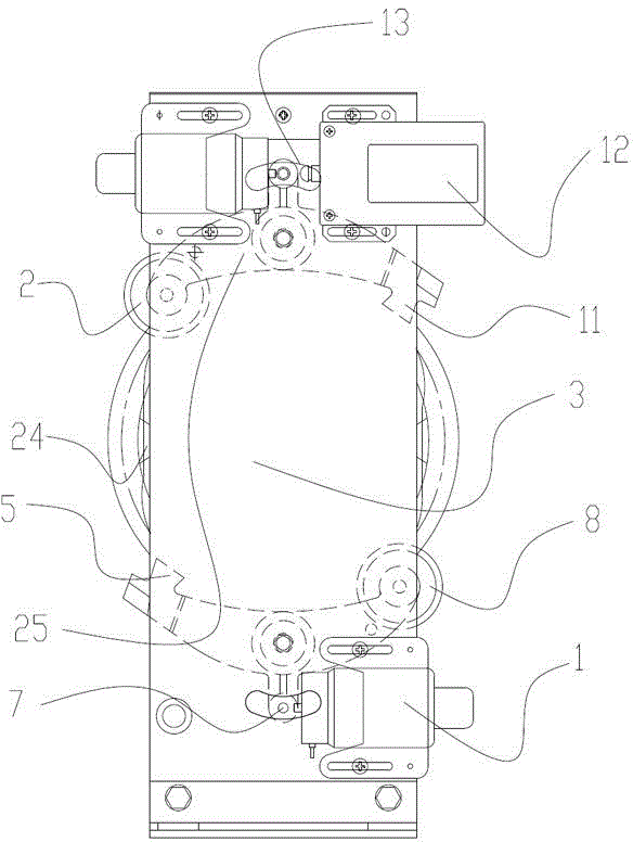
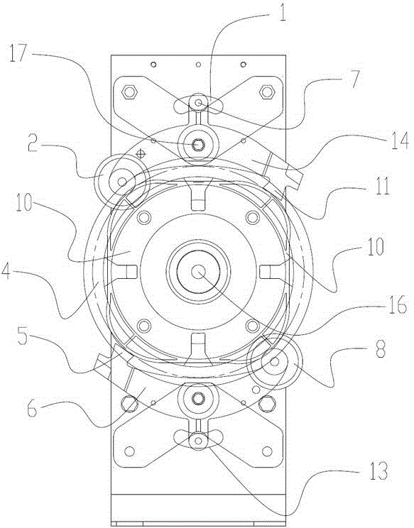
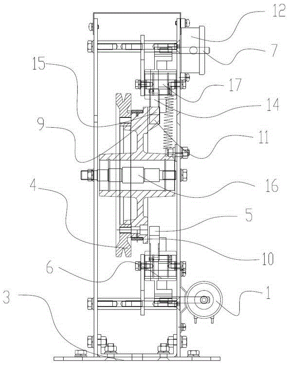
[0021] Such as figure 1 , figure 2 and image 3 As shown, the speed limiter with anti-rolling device described in this embodiment includes a support frame 3 and a main shaft 16, the two ends of the main shaft 16 are connected with the support frame 3, and the support frame 3 is connected with a swing rod through a swing shaft 17 device 25, the swing rod device 25 includes an upper swing rod 14 and a lower swing rod 6, a sheave device 24 is sleeved on the main shaft 16, the upper swing rod 14 is located above the sheave device 24, and the lower swing rod 6 is located at the sheave device 24 The bottom of the upper swing rod 14 is symmetrical to each other, and the middle part of the upper swing rod 14 and the lower swing rod 6 is provided with an action rod 7, and the upper swing rod 14 and the lower swing rod 6 are connected to the support frame 3 through the swing shaft 17; Sheave device 24 comprises cable sheave 9 and sheave 4, sheave 4 is fixed on the front end of sheave...

Embodiment 2

[0025] Such as Figure 4 and Figure 5 As shown, the speed limiter with anti-rolling device described in this embodiment is different from Embodiment 1 in that: the first spring shaft 19 is fixed at one end of the upper swing rod 14 provided with the upper roller 2, and the first One end of the first extension spring 20 is fixed on the spring shaft 19, and the second spring shaft 18 is also fixed on the support frame 3, and the other end of the first extension spring 20 is fixed on the support frame 3 by the second spring shaft 18, One end of the lower swing rod 6 provided with the lower roller 8 is fixed with a third spring shaft 22, and one end of the second extension spring 21 is fixed on the third spring shaft 22, and a fourth spring shaft 23 is also fixed on the support frame 3. , the other end of the second tension spring 21 is fixed on the support frame 3 through the fourth spring shaft 23 .

[0026] Compared with Embodiment 1, the speed limiter with anti-rolling devi...


PUM


Abstract

The invention discloses a speed limiter with a car slipping preventive device. The speed limiter is characterized in that two ends of a spindle are connected with a support frame, a swing rod device is connected onto the support frame by swing shafts and comprises an upper swing rod and a lower swing rod, a rope pulley device sleeves the spindle, the upper swing rod is positioned above the rope pulley device, the lower swing rod is positioned below the rope pulley device and is symmetrical with the upper swing rod, actuating struts are arranged in the middle of the upper swing rod and the middle of the lower swing rod respectively, and the upper swing rod and the lower swing rod are connected with the support frame by the swing shafts. The speed limiter has the advantages that when a car of an elevator slips and the slipping distance of the car is farther than a distance set by a travel switch, the elevator can be braked; when the speed of the elevator is higher than a speed set by the speed limiter, the speed limiter can be mechanically actuated, and then safe pliers or a rope gripper can be driven to be actuated, so that the elevator can stop and is high in safety and reliability.

Description

technical field [0001] The invention relates to a speed governor with an anti-rolling device used in an elevator device. Background technique [0002] With the progress of society, elevators are used more and more widely in social life, and higher requirements are put forward for the equipment in the elevator industry. At present, there are many types of speed limiters. For example, the patent number is: 200620004641.5. The speed governor includes a sheave assembly, a swinging part and a bracket, and is characterized in that: the sheave part includes a ratchet, a sheave fixedly installed on the ratchet and wound with a speed governor rope, and four sides to the ratchet mounted on the ratchet through connecting pins. An octagonal disc-shaped cam, one end plane of the ratchet has 4-8 ratchets evenly distributed, the sheave part is installed on the bracket through the bearing and the sheave shaft, and the swing part includes a crescent-shaped pendulum , the pendulum is install...

Claims


Application Information

Patent Timeline
Patent Type & Authority Applications(China)
IPC IPC(8): B66B5/04B66B5/24
Inventor 柳明国周海波
Owner NINGBO OULING ELEVATOR COMPONENTS
Why Eureka
Try Eureka