
A wheel hub lifting jig

A hoisting and jig technology, applied in the directions of transportation and packaging, load hoisting components, etc., can solve the problems of uneven heating and cooling of the hub, large time gap, limited size of the hub, etc., to avoid deformation problems, increase the safety factor, increase the The effect of high friction

Inactive Publication Date: 2016-04-27
HENAN UNIV OF SCI & TECH +1
View PDF7 Cites 0 Cited by
  • Summary
  • Abstract
  • Description
  • Claims
  • Application Information

AI Technical Summary

Problems solved by technology

There are two types of hub parts: one is that the "U" groove is located on the outer edge of the hub, such as pulleys and car wheels, and the other is that the "U" groove is located on the inner edge of the hub, such as brake drums. However, at present The hub lifting fixtures used are only for a certain type of hub, for example, the hub with the "U" groove on the outer edge or the hub with the "U" groove on the inner edge. There is no device that can complete the described The hoisting of the two types of hubs needs to be replaced with different fixtures according to the hoisted hubs during use, which is very troublesome and inefficient, and the size of the hubs that can be hoisted is limited, so the scope of application is relatively limited
In addition, at present, manual binding of steel wire ropes is often used to hoist the hub for quenching treatment. On the one hand, manual binding is time-consuming and there are safety issues. Large, resulting in uneven heat and cold of the hub, easy to heat expansion and contraction deformation, seriously affecting the production quality of the hub

Method used


Image

  • A wheel hub lifting jig

Examples


Embodiment Construction

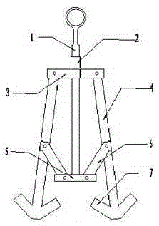
[0018] A hub hoisting jig mainly includes a suspension shaft 1, a sleeve 2, a square plate 3, a mechanical arm 4, a weight 5, a connecting rod 6, and an anchor-shaped manipulator grip 7, wherein the suspension shaft 1 is located in the sleeve 2 and can be Move up and down, the sleeve 2 is welded to the center of the square plate 3, the lower end of the suspension shaft 1 is welded to the weight 5, the mechanical arm 4 is connected to the side of the square plate 3 through pins, and the end of the connecting rod 6 is connected to the weight 5 through the pins. The other end is rotationally connected with the mechanical arm 4, and the anchor-shaped manipulator grip 7 is welded to the lower end of the mechanical arm 4, wherein the mechanical arm 4, the connecting rod 6 and the square plate 3 are made of triangle iron, and the anchor-shaped manipulator grip 7 is made of square steel pipe The size of the weight 5 is much smaller than the size of the square plate 3. The limit positio...


PUM


Abstract

A wheel hub hoisting fixture mainly comprises a hoisting shaft, a sleeve, a square plate, mechanical arms, a counterweight, connecting rods and anchor-shaped mechanical claws, wherein the hoisting shaft is positioned inside the sleeve and can move up and down; the sleeve is fixedly connected with the square plate; the lower end of the hoisting shaft is fixedly connected with the counterweight; the mechanical arms are rotatably connected with the square plate through pins; one end of each of the connecting rods is rotatably connected with the counterweight through a pin; the other end of each of the connecting rods is rotatably connected with one mechanical arm; the mechanical claws are fixedly connected with the lower ends of the mechanical arms. The wheel hub hoisting fixture has the benefits as follows: the anchor-shaped mechanical claws can conveniently hoist a wheel hub, of which a U-shaped groove is positioned in the outer edge or inner edge of the wheel hub, so that time and manpower cost are saved, and the wheel hub is transversely hoisted for quenching, so that the problem of deformation caused by non-uniform heating is avoided, and the qualified rate of products is improved.

Description

technical field [0001] The invention relates to a device for hoisting heavy objects in a hoisting machine, in particular to a fixture for hoisting a wheel hub. Background technique [0002] Wheel parts are widely used in the field of machinery, especially in the field of vehicle manufacturing. Some wheel hubs are relatively large in volume and weight, and are not easy to lift. There are two types of hub parts: one is that the "U" groove is located on the outer edge of the hub, such as pulleys and car wheels, and the other is that the "U" groove is located on the inner edge of the hub, such as brake drums. However, at present The hub lifting fixtures used are only for a certain type of hub, for example, the hub with the "U" groove on the outer edge or the hub with the "U" groove on the inner edge. There is no device that can complete the described The hoisting of the two types of hubs needs to be replaced with different fixtures according to the hoisted hubs during use, whic...

Claims


Application Information

Patent Timeline
Patent Type & Authority Patents(China)
IPC IPC(8): B66C1/44
Inventor 许媛媛闫焉服王新阳祝文公王新各王红娜夏月庆
Owner HENAN UNIV OF SCI & TECH
Learn More