Fatigue wear tester for rubber material

A wear test, rubber material technology, applied in the direction of testing wear resistance, etc., can solve the problems of rubber material damage, fatigue and wear can not be considered

Inactive Publication Date: 2014-05-28
SHENYANG POLYTECHNIC UNIV
View PDF5 Cites 0 Cited by
  • Summary
  • Abstract
  • Description
  • Claims
  • Application Information

AI Technical Summary

Problems solved by technology

[0005] Purpose of the invention: the present invention provides a fatigue wear testing machine for rubber materials, the purpose of which is to solve the problem that the rubber fatigue testing machine or the rubber wear testing machine cannot consider the interaction between fatigue and wear to damage the rubber material

Method used


Image

  • Fatigue wear tester for rubber material
  • Fatigue wear tester for rubber material
  • Fatigue wear tester for rubber material

Examples


specific Embodiment approach

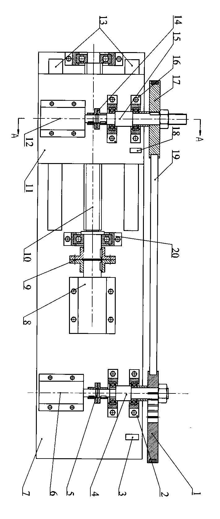
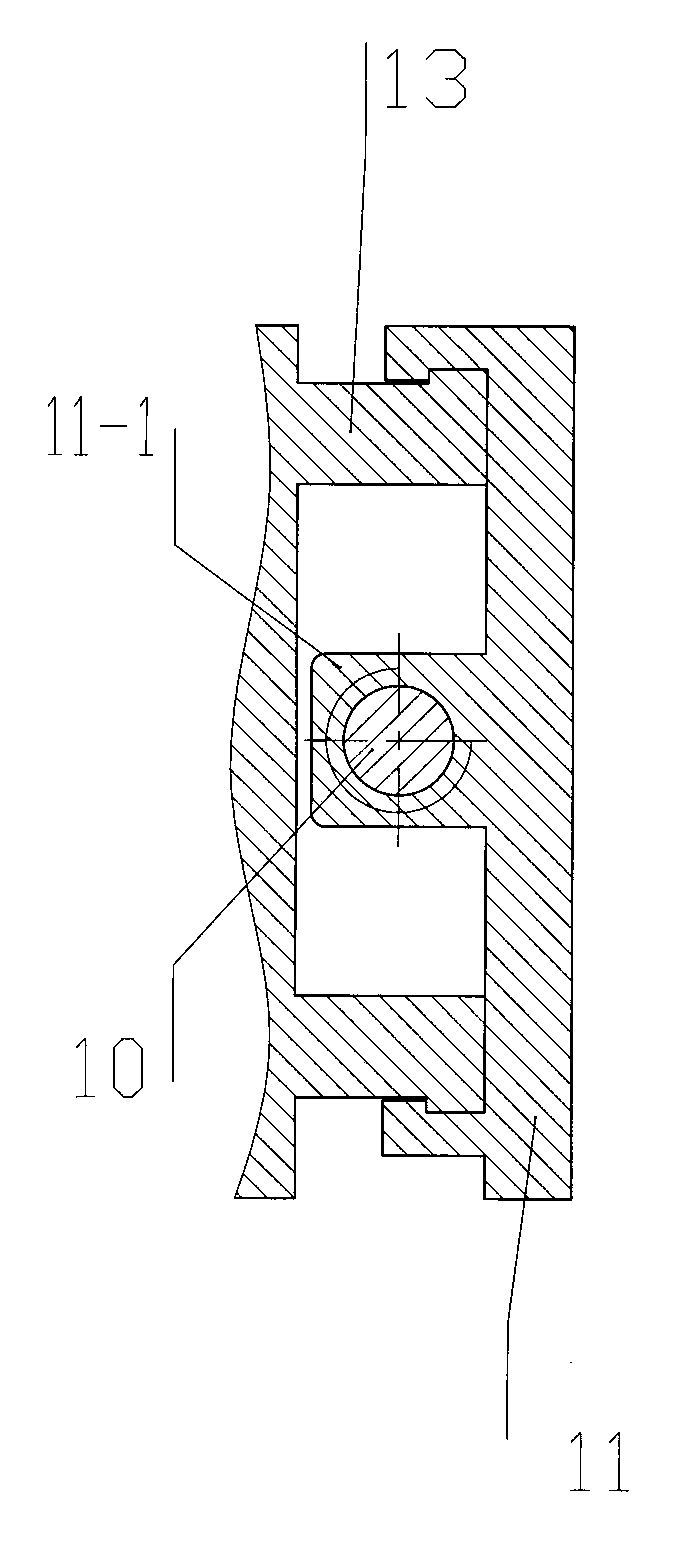
[0034] like figure 1 As shown in and 11, the adjustment wheel on the dynamic actuator is a concentric pulley 17 or a pulley 7-6; the concentric pulley 17 is fixed with the shaft 15 of the dynamic actuator through a key; as shown in Figures 5 and 6, the concentric pulley 17 and the pulley 7-6 are cylindrical cake-shaped structures, and have grooves for installing samples on the outer surface of the cylinder.

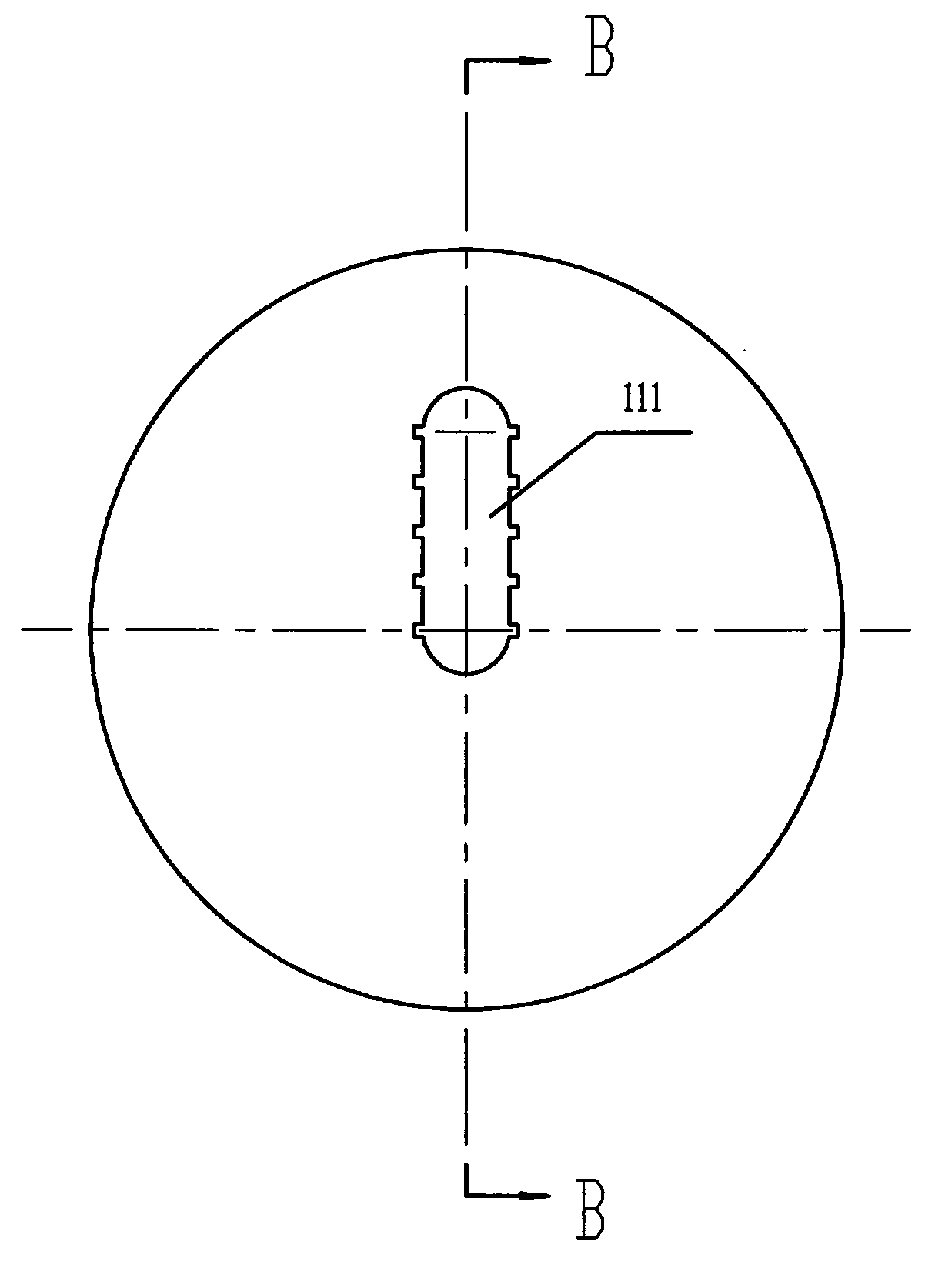
[0035] The adjustment mechanism on the fixed actuator is an adjustable pulley 1 or a composite mechanism composed of a crankshaft 7-1 and an auxiliary pulley 7-2; as shown in Figures 3 and 4, the adjustable pulley 1 is a cylindrical pie structure, There is a long hole 111 in the radial direction, the center of one end of the long hole coincides with the center of the pulley, and a symmetrical keyway is opened on the inner wall surface of the long hole 111, and the long hole 111 is set on the fixed actuator. On the shaft 4 and fixed by a key inserted in the keyway, there...


PUM


Abstract

The invention provides a fatigue wear tester for a rubber material. The fatigue wear tester comprises a belt wheel, a bearing pedestal, an eccentric wheel, a shaft, a shaft coupling, a servo motor, a leading screw, a guide rail, a tachometer, a sliding table and a tester body. The fatigue wear tester provided by the invention overcomes the problem that influence of interaction between fatigue and wearing on damage of the rubber material cannot be tested by a fatigue tester or a wear tester for rubber.

Description

technical field [0001] The invention relates to material testing technology, in particular to a testing device capable of performing fatigue wear tests on rubber materials. Background technique [0002] Compared with other artificial lift technologies (such as plunger pumping unit, electric submersible centrifugal pump, etc.), submersible screw pump oil production technology is suitable for high viscosity and high sand content crude oil production. The application in heavy oil wells in Dagang, Liaohe, Shengli and other oil fields has expanded rapidly, making outstanding contributions to the country's energy development. [0003] The rubber stator of the submersible screw pump, in the long-term rolling and sliding operation of the rotor, is worn by the rotor on the one hand and subjected to alternating stress on the other hand, resulting in fatigue cracks. Once the rubber stator cracks, it will inevitably increase its wear rate, which will reduce the efficiency of the screw ...

Claims


Application Information

Patent Timeline
IPC IPC(8): G01N3/56
Inventor 闫明刘栋佟玲吕晓仁王世杰
Owner SHENYANG POLYTECHNIC UNIV
Why Eureka
Try Eureka