Fatigue wear testing machine for rubber materials

A wear test and rubber material technology, applied in the direction of testing wear resistance, etc., can solve the problems of rubber material damage, fatigue and wear can not be considered

Inactive Publication Date: 2016-06-01
SHENYANG POLYTECHNIC UNIV
View PDF5 Cites 0 Cited by
  • Summary
  • Abstract
  • Description
  • Claims
  • Application Information

AI Technical Summary

Problems solved by technology

[0005] Purpose of the invention: the present invention provides a fatigue wear testing machine for rubber materials, the purpose of which is to solve the problem that the rubber fatigue testing machine or the rubber wear testing machine cannot consider the interaction between fatigue and wear to damage the rubber material

Method used


Image

  • Fatigue wear testing machine for rubber materials
  • Fatigue wear testing machine for rubber materials
  • Fatigue wear testing machine for rubber materials

Examples


specific Embodiment approach

[0034] Detailed ways: Below in conjunction with accompanying drawing, the present invention will be further described:

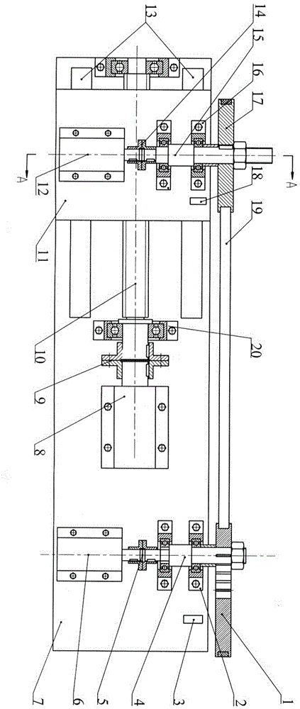
[0035] like figure 1 As shown, the present invention provides a kind of fatigue wear testing machine of rubber material, and this testing machine comprises machine base 7, two test actuators and test distance adjustment mechanism; Two test actuators are respectively moving actuator and fixed actuator, The dynamic actuator is arranged on the test distance adjustment mechanism, and the test distance adjustment mechanism and the fixed actuator are arranged on the base 7; the dynamic actuator includes the first servo motor 12, the shaft 15 connected with the first servo motor 12 and the The adjustment wheel at the front end of 15; the fixed actuator includes the shaft 4 connected to the second servo motor 6 and the adjustment mechanism arranged at the front end of the shaft 4; the shaft 15 connected with the first servo motor 12 and the shaft 15 connected wit...


PUM


Abstract

The invention provides a fatigue wear testing machine for rubber materials, which includes a pulley, a bearing seat, an eccentric wheel, a shaft, a shaft coupling, a servo motor, a lead screw, a guide rail, a speedometer, a sliding table and a fuselage. The fatigue testing machine or the rubber wear testing machine cannot consider the interaction of the two factors of fatigue and wear on the damage to the rubber material.

Description

technical field [0001] The invention relates to material testing technology, in particular to a testing device capable of performing fatigue wear tests on rubber materials. Background technique [0002] Compared with other artificial lift technologies (such as plunger pumping unit, electric submersible centrifugal pump, etc.), submersible screw pump oil production technology is suitable for high viscosity and high sand content crude oil production. The application in heavy oil wells in Dagang, Liaohe, Shengli and other oil fields has expanded rapidly, making outstanding contributions to the country's energy development. [0003] The rubber stator of the submersible screw pump, in the long-term rolling and sliding operation of the rotor, is worn by the rotor on the one hand and subjected to alternating stress on the other hand, resulting in fatigue cracks. Once the rubber stator cracks, it will inevitably increase its wear rate, which will reduce the efficiency of the screw ...

Claims


Application Information

Patent Timeline
Patent Type & Authority Patents(China)
IPC IPC(8): G01N3/56
Inventor 闫明刘栋佟玲吕晓仁王世杰
Owner SHENYANG POLYTECHNIC UNIV
Why Eureka
Try Eureka