Grounding device for high-soil resistivity region

A soil resistivity and grounding device technology, applied in the direction of connecting contact materials, etc., can solve the problems of difficulty in reducing grounding resistance, insufficient grounding area, and poor use effect.

Active Publication Date: 2014-05-28
STATE GRID CORP OF CHINA +1
View PDF14 Cites 9 Cited by
  • Summary
  • Abstract
  • Description
  • Claims
  • Application Information

AI Technical Summary

Problems solved by technology

In areas with high soil resistivity, this design generally requires a long grounding body, and the grounding resistance is too large, but the area of ​​the grounding body is insufficient. In areas with high soil resistivity or limited by terrain , it is often difficult to meet the requirements of reducing the grounding resistance, and the use effect is poor

Method used


Image

  • Grounding device for high-soil resistivity region
  • Grounding device for high-soil resistivity region
  • Grounding device for high-soil resistivity region

Examples


Embodiment Construction

[0019] The present invention is described in detail below in conjunction with accompanying drawing:

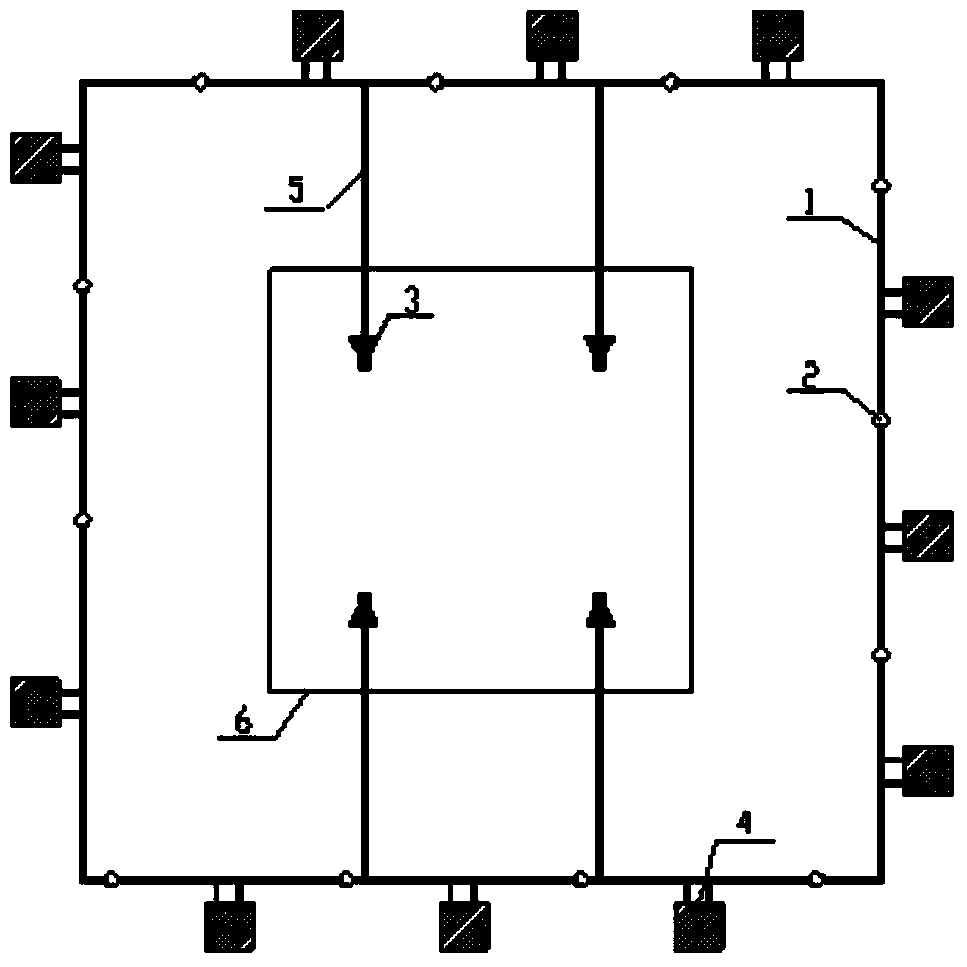
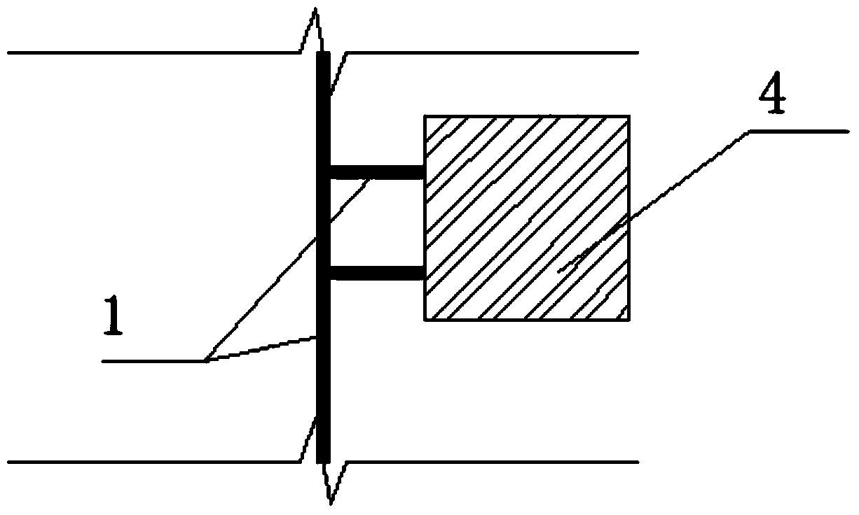
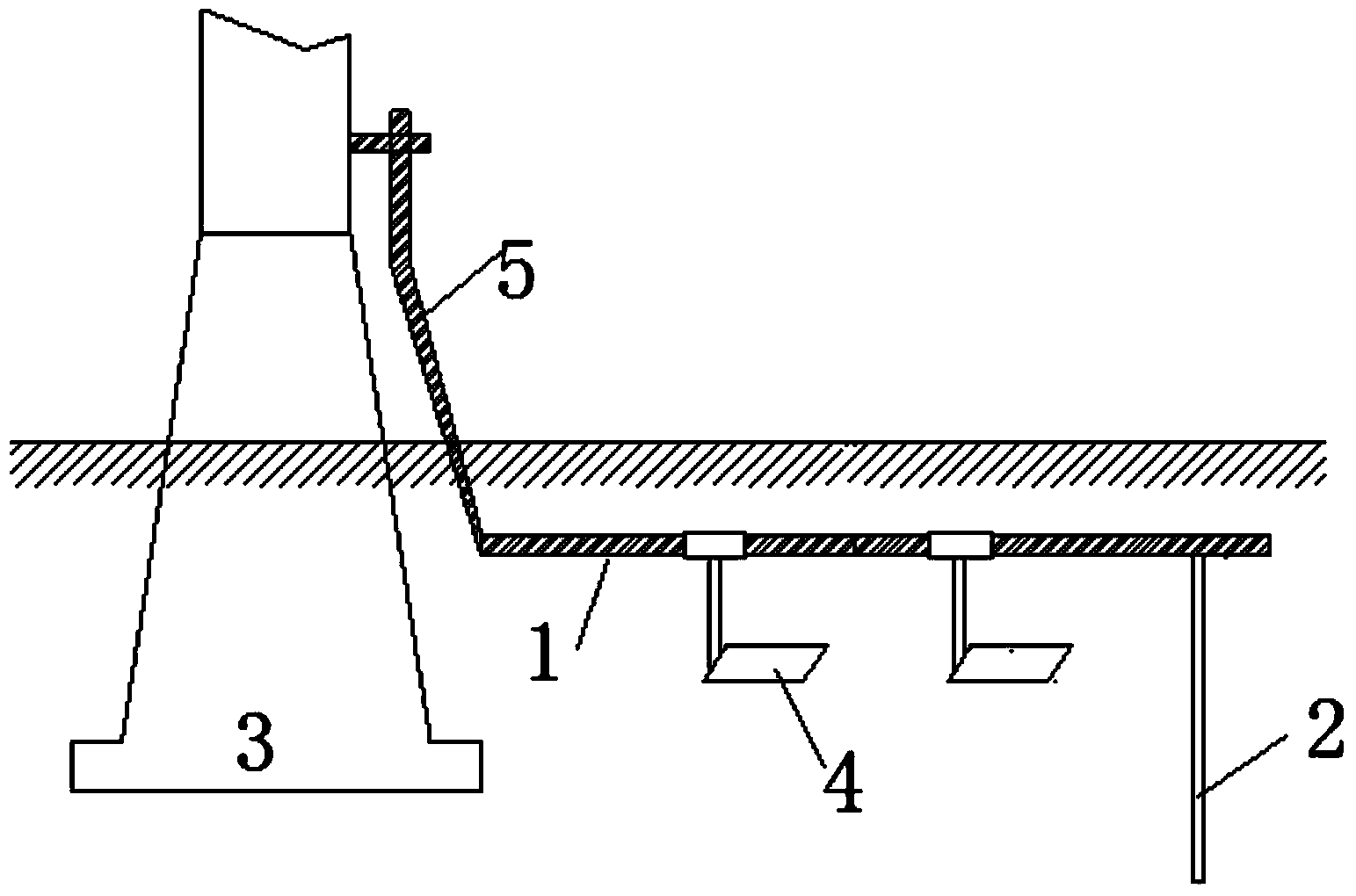
[0020] Such as Figure 1-3 As shown, the grounding device in a high soil resistivity area, the grounding device includes a plurality of grounding plates 4, each grounding plate 4 is installed on the periphery of the grounding flat steel 1, and a plurality of grounding electrodes 2 are also arranged on the grounding flat steel 1, The ground flat steel 1 is also welded to the upper part of the tower through the lightning protection down conductor 5 of the tower, and the tower is fixed on the ground through the tower foot 3;

[0021] The ground flat steel 1 has ground poles 2 as nodes, and a ground plate 4 is provided between every two adjacent nodes.

[0022] The grounding plate 4 and the grounding flat steel 1 are welded by two round steels, and the welded round steels are 20cm long connecting devices.

[0023] The ground flat steel 1 is square.

[0024] The grounding plate ...


PUM


Abstract

The invention discloses a grounding device for a high-soil resistivity region. The grounding device comprises a plurality of grounding plates, wherein each grounding plate is mounted at the periphery of grounding flat steel; a plurality of grounding electrodes are also arranged on the grounding flat steel; the grounding flat steel is also welded to the upper part of a pole tower through a pole tower anti-thunder down lead; the pole tower is fixed on the ground through pole tower support legs; the grounding flat steel takes the grounding electrodes as nodes, and each grounding plate is arranged between every two adjacent nodes. The grounding area can be effectively enlarged, the value of the grounding resistance can be reduced, and the anti-thunder level of a circuit is increased.

Description

technical field [0001] The invention relates to a grounding device for areas with high soil resistivity. Background technique [0002] Most of the existing tower grounding devices use ordinary round steel and flat steel strips added to the tower legs of each tower as the grounding body. In areas with high soil resistivity, this design generally requires a long grounding body, and the grounding resistance is too large, but the area of ​​the grounding body is insufficient. In areas with high soil resistivity or limited by terrain , it is often difficult to meet the requirements of reducing the grounding resistance, and the use effect is poor. Contents of the invention [0003] In order to solve the deficiencies in the prior art, the invention discloses a grounding device in areas with high soil resistivity, which can effectively increase the grounding area, reduce the grounding resistance, and improve the level of lightning protection. [0004] To achieve the above object,...

Claims


Application Information

Patent Timeline
IPC IPC(8): H01R4/66
Inventor 李尚振亓延峰柳絮洁李岩李清泉任昂李英王立新毕胜华李淑云段伦峰李鹏陈顺东裴秀高毛军江婷婷毕经国陈利周庆张鹏
Owner STATE GRID CORP OF CHINA
Why Eureka
Try Eureka