Small-sized plane wideband antenna capable of filtering

A broadband antenna and planar technology, applied in the field of filterable planar broadband antennas, can solve the problems of large bandwidth, high antenna sensitivity, and large size, and achieve the effects of reducing the overall size, expanding the ground area, and reducing sensitivity

Inactive Publication Date: 2009-05-13
UNIV OF SCI & TECH OF CHINA
View PDF1 Cites 9 Cited by
  • Summary
  • Abstract
  • Description
  • Claims
  • Application Information

AI Technical Summary

Problems solved by technology

However, due to its narrowband system and non-planar structure, it is not conducive to practical application
[0003] The International Institute of Electrical and Electronics Engineers "Antennas and Propagation International Symposium, 2007 IEEE" introduced a microstrip antenna-filter based on a coupled parallel stripline structure for 3 to 5G system, but the port impedance of the system is matched to 60 ohms, there is no effective way to give actual measurement results, and the size is large, which is not conducive to practical application
[0004] The International Institute of Electrical and Electronics Engineers "Antennas and Propagation International Symposium, 2007 IEEE" introduced an antenna filter system applied to 3 to 10G, but its in-band response is not good, and the size Larger, more inconvenient in application
[0005] China Patent Application No. 200810123432.6 proposes a miniaturized planar ultra-wideband time-domain antenna. Its impedance bandwidth can cover the 3.1GHz-10.6GHz frequency band, and it is easy to feed and manufacture; but because the antenna is a tapered structure, its bandwidth is very large , can only complete the function of radiating energy into space, without out-of-band suppression, and the performance of the antenna is highly sensitive to the application environment

Method used


Image

  • Small-sized plane wideband antenna capable of filtering
  • Small-sized plane wideband antenna capable of filtering
  • Small-sized plane wideband antenna capable of filtering

Examples


Embodiment 1

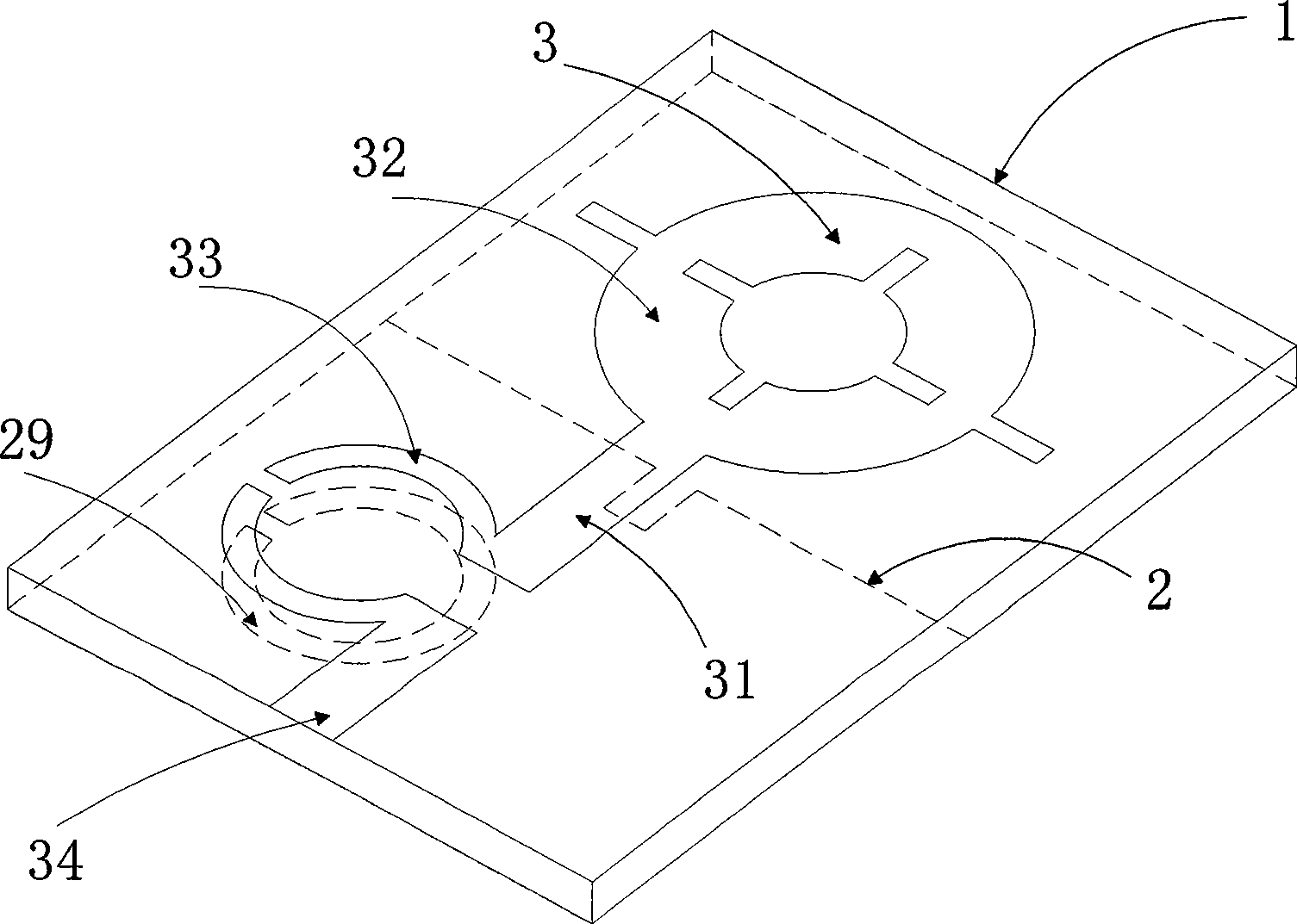
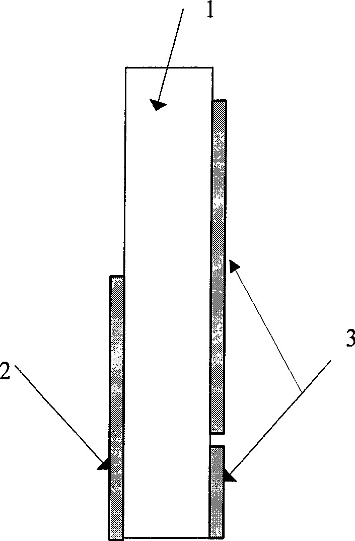
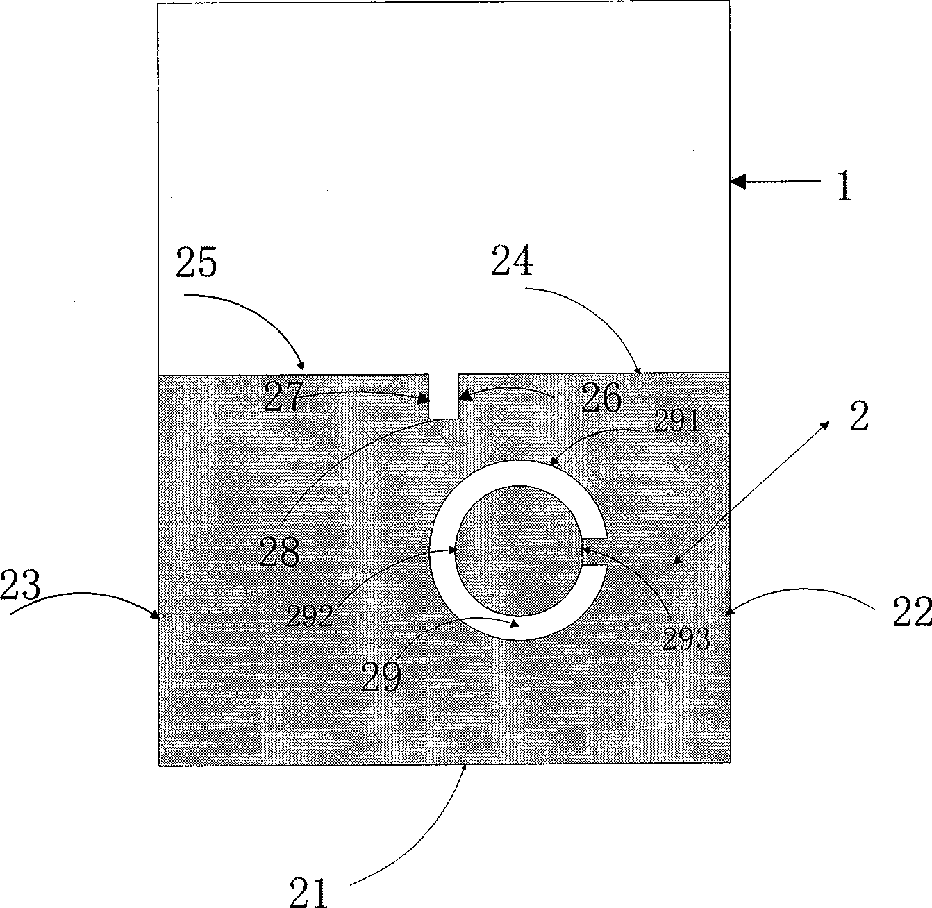
[0020] This embodiment can filter the shape and structure of the small planar broadband antenna and the matching connection relationship between the parts, see figure 1 The schematic diagram of the structure is given, figure 2 given side view, image 3 given the rear view and Figure 4 Front view given. It consists of three parts including a dielectric substrate 1 and a radiating metal layer 3 and a grounding metal layer 2 respectively printed on the front and back planes of the dielectric substrate.

[0021] The dielectric substrate 1 has a width of 20-40mm, a length of 35mm-50mm, a dielectric constant of 2.0-8.0, and a thickness of 0.5-5.0mm. Feed metal layer. In order to reduce the influence of the dielectric plate on the field distribution at the coupling structure, a dielectric substrate with a lower dielectric constant (2.0-5.0) is usually used, and a thinner thickness (0.5-2.0mm) is selected when the hardness is suitable. In this implementation example, the dielec...


PUM


Abstract

The invention discloses a filtering small planar wideband antenna which is characterized in that rectangular openings that are just opposite to a center are cut off from the two ends of an annular strip, two sections of upper and lower rectangular transmission strips are respectively taken as a connecting line of an annular radiation unit and the strip and a microstrip feed structure to be respectively connected with the right end of the upper part and the right end of the lower part of the annular strip, a rectangular opening slot with bilateral symmetry is cut off from the upper edge of a grounding rectangular metal layer along the middle, and an annular opening slot is broken to be in the non-closed state at the positions which are corresponding to the openings of the annular strip that are just opposite to the center; the antenna radiation unit is followed and connected by a small filter unit to expand the grounding area of the antenna, and the overall size is reduced due to the unbalanced feed structure; the filtering small planar wideband antenna can not only efficiently radiate the energy in the working band into space, but also have good inhibition function for outband signals, thereby reducing the sensitivity of the whole system to the application environment; and the working bandwidth is 3.1GHz-5.2GHz. The antenna is easy to feed and to be produced and can be effectively applied in wideband wireless communication systems.

Description

technical field [0001] The invention belongs to the technical field of broadband antennas and passive devices, and in particular relates to a filterable planar broadband antenna co-designed with a broadband antenna and a broadband filter. Background technique [0002] The International Institute of Electrical and Electronics Engineers "Microwave Theory and Technology" magazine (IEEE Transaction on Microwave Theory and Technology, Vol.55, No.9, June.2007, p1182-1189) introduced an antenna-filter applied to the K-band Mutual Synthesis of Combined Microwave Circuits Applied to the Design of a Filter-Antenna Subsystem, reflecting that the system using collaborative design can be smaller in size and stronger in function than traditional design. But because it is a narrowband system and non-planar structure, it is not conducive to practical application. [0003] The International Institute of Electrical and Electronics Engineers "Antennas and Propagation International Symposium, ...

Claims


Application Information

Patent Timeline
Patent Type & Authority Applications(China)
IPC IPC(8): H01Q1/38H01Q13/08H01P1/20
CPCY02B60/50
Inventor 周杰美王俊王卫东张琼
Owner UNIV OF SCI & TECH OF CHINA
Why Eureka
Try Eureka