Rotating multi-channel power transmission device

A multi-channel power transmission device, brush technology, applied in the direction of rotating current collectors, circuits, current collectors, etc., can solve the problems of circuit disconnection, large size, loose contact between brushes and conductive rods, etc., to ensure contact reliability. , to ensure the effect of conduction

Active Publication Date: 2014-05-28
BEIJING INST OF AEROSPACE CONTROL DEVICES
View PDF4 Cites 7 Cited by
  • Summary
  • Abstract
  • Description
  • Claims
  • Application Information

AI Technical Summary

Problems solved by technology

The disadvantage is that the contact force between the brush and the conductive rod is not easy to control. When the contact force is too large, the friction force between the brush and the conductive rod will be large, which will generate a large disturbance torque to the brush assembly; when the contact force is too high Hours, the contact between the brush and the conductive rod is loose, which is easy to disconnect the circuit
In order to facilitate the installation of the power transmission device, a flange with a threaded hole is usually provided at one end of the bracket, and the flange is fixed to the outside with screws, so as to realize the fixed installation of the power transmission device. There are certain requirements, especially when the flange needs to be installed inside the instrument equipment, it is difficult to disassemble, which is not conducive to the maintenance and replacement of the power transmission device. When simultaneous transmission of multiple signals is required and there are strict requirements for safety, For example, in high-precision instruments, a multi-channel signal transmission device with compact structure, reliable power transmission and easy disassembly is required.

Method used


Image

  • Rotating multi-channel power transmission device
  • Rotating multi-channel power transmission device
  • Rotating multi-channel power transmission device

Examples


Embodiment Construction

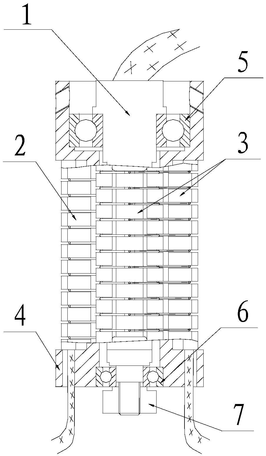
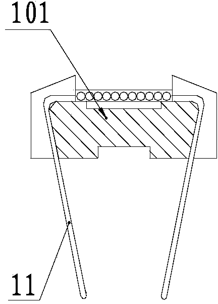
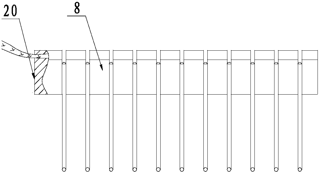
[0020] Such as figure 1 As shown, the high-reliability miniature rotary multiple power transmission device of the present invention includes a conductive rod 1, a first brush part 2, a second brush part 3, and a bracket 4. The conductive rod 1 is installed inside the bracket 4, and the conductive rod 1 It can rotate relatively freely with the bracket 4; the first brush part 2 and the second brush part 3 are fixed on the bracket 4; the structure and composition of the first brush part 2 and the second brush part 3 are the same. The first brush part 2 and the second brush part 3 are both composed of a U-shaped brush assembly 8 and an L-shaped brush assembly 9, so that the first brush part 2 and the second brush part 3 have multiple layers The brushes are insulated from each other; the U-shaped brush assembly 8 and the L-shaped brush assembly 9 are both fixedly connected to the bracket 4 by means of cementing. The brushes of the first brush member 2 and the second brush member 3 a...


PUM


Abstract

The invention discloses a rotating multi-channel power transmission device. The rotating multi-channel power transmission device comprises a conducting rod (1), a first electric brush component (2), a second electric brush component (3) and a support (4); and the first electric brush component (2) and the second electric brush component (3) are respectively composed of a U-shaped electric brush assembly (8) and an L-shaped electric brush assembly (9), wherein the U-shaped electric brush assembly (8) is composed of a U-shaped frame (101) and U-shaped electric brushes (11) bonded on each slot of the U-shaped frame (101), and the L-shaped electric brush assembly (9) is composed of an L-shaped electric brush frame (102) and L-shaped electric brushes (12) which are bonded on each slot of the L-shaped electric brush frame (102). The first electric brush component and the second electric brush component are in three-point contact with the conducting rod, and therefore, the reliability of the contact of the electric brush assemblies and slip rings can be ensured, and the conduction of a circuit can be ensured.

Description

Technical field [0001] The invention relates to a rotary multi-channel power transmission device. Background technique [0002] The power transmission device requires high reliability, and the power transmission device currently used is easy to assemble. Generally, there are two slip ring contact points between the brush and the conductive rod. The conductive rod is composed of a slip ring shaft, a conductive slip ring, and an insulating layer between the conductive slip ring. The disadvantage is that the contact force between the brush and the conductive rod is not easy to control. When the contact force is too large, the friction force of the contact between the brush and the conductive rod is relatively large, which produces a large interference torque on the brush assembly; When it is small, the contact between the brush and the conductive rod is loose, and it is easy to break the circuit. In order to facilitate the installation of the power transmission device, a flange wi...

Claims


Application Information

Patent Timeline
Patent Type & Authority Applications(China)
IPC IPC(8): H01R39/64H01R39/24
Inventor 王昕严小军张福礼刘钦马笑笑李南婷岳辉
Owner BEIJING INST OF AEROSPACE CONTROL DEVICES
Why Eureka
Try Eureka