
Coil wiring element and method for manufacturing coil wiring element

A manufacturing method and wiring technology, which can be applied to coils, electrical components, and the size/direction of the magnetic field, which can solve the problems of difficult to form and difficult to form high-density winding coil wiring.

Inactive Publication Date: 2014-05-28
THE FUJIKURA CABLE WORKS LTD
View PDF7 Cites 2 Cited by
  • Summary
  • Abstract
  • Description
  • Claims
  • Application Information

AI Technical Summary

Problems solved by technology

Therefore, it is difficult to form the fine second wiring layer 106 with high precision, and as a result, it is difficult to form high-density wound coil wiring.

Method used


Image

  • Coil wiring element and method for manufacturing coil wiring element
  • Coil wiring element and method for manufacturing coil wiring element
  • Coil wiring element and method for manufacturing coil wiring element

Examples


Embodiment Construction

[0049] Hereinafter, the present invention will be described based on preferred embodiments with reference to the drawings.

[0050]

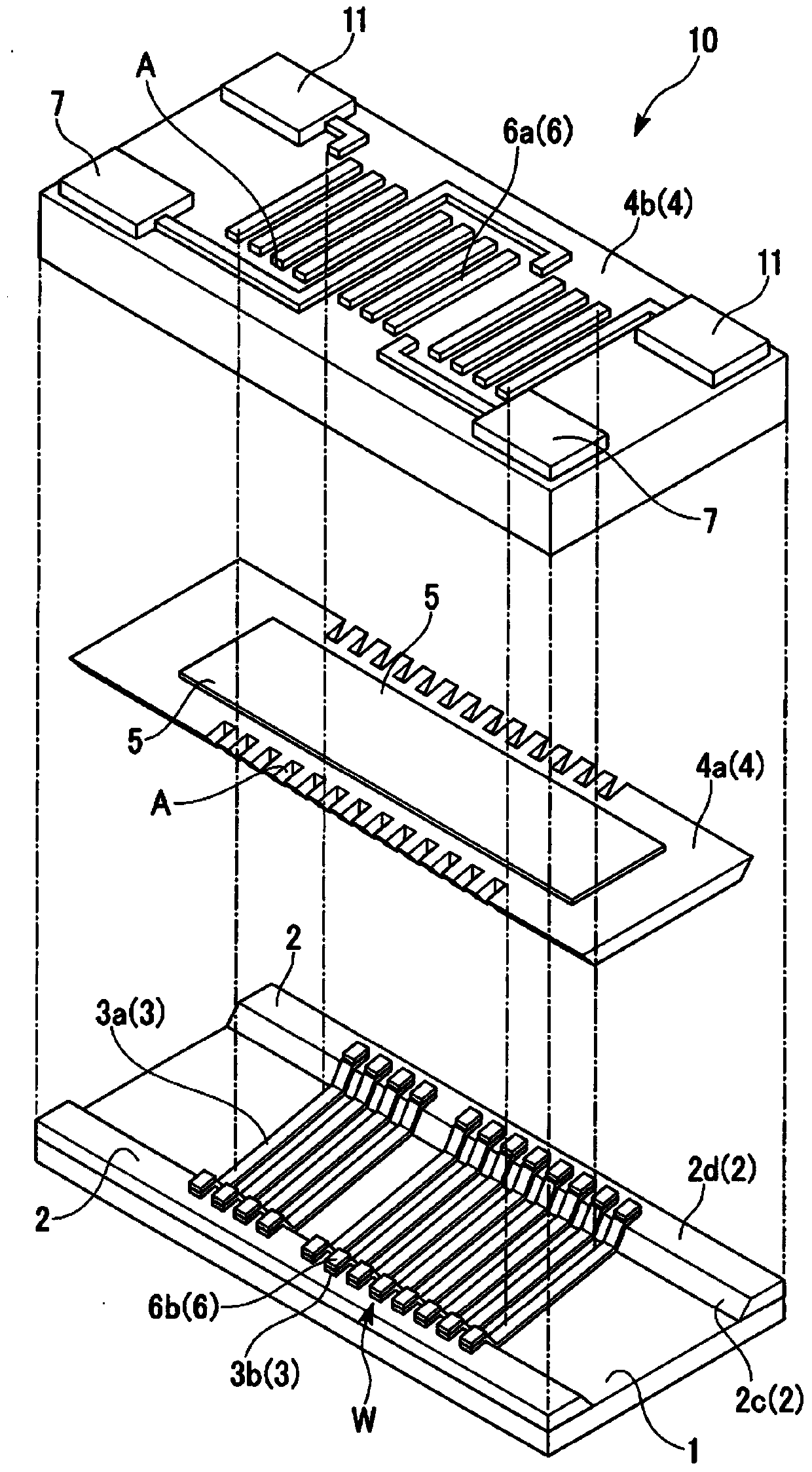
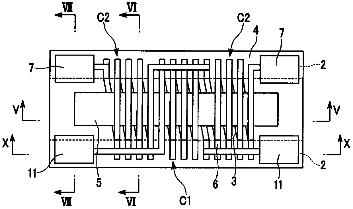
[0051] figure 1 It is an exploded perspective view showing the coil wiring element 10 according to the first embodiment of the present invention. In this exploded perspective view, it is divided into a member group consisting of the substrate 1, the second resin part 2 and the first wiring 3, and a first part 4a (part of the first resin part 4) of the first resin part 4 and a magnetic body ( The component group consisting of the magnetic core) 5 and the component group consisting of the second part 4 b of the first resin part 4 (other parts of the first resin part 4 ) and the second wiring 6 are shown as if separated from each other. figure 2 It is a perspective view in which the first resin part 4 is transparently shown from above.

[0052] The coil wiring element 10 has: a plurality of first wirings 3 (lower side wirings) formed on a sub...


PUM


Abstract

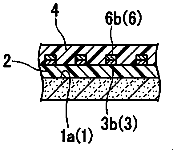
A coil wiring element and a method for manufacturing the coil wiring element are provided. The coil wiring element of the present invention is provided with: a plurality of first wiring lines (3), each of which is formed on a substrate (1), and has a center portion (3a) and both the edge portions (3b); second resin sections (2), which are formed on the substrate (1), and support both the edge portions (3b) of each of the first wiring lines (3); a first resin section (4) that covers the center portion (3a) of each of the first wiring lines (3); a plurality of second wiring lines (6), each of which is formed on the first resin section (4), and has both the end portions (6b); bonding sections (W), which bond the first wiring lines (3) and the second wiring lines (6), and are supported by the second resin sections (2); and a coil wiring line, which has the end portions (3a) of the first wiring lines (3) and the end portions (6a) of the second wiring lines (6) sequentially bonded therein, and is spirally wound on the first resin portion (4).

Description

technical field [0001] The present invention relates to a coil wiring element and a method of manufacturing the coil wiring element. More specifically, the present invention relates to a coil wiring component formed by laminating conductor layers and insulating layers on a substrate, and a method of manufacturing the coil wiring component using a thin film process. [0002] this application claims priority based on Japanese Patent Application No. 2011-211749 for which it applied on September 28, 2011, The content is used in this specification. Background technique [0003] In recent years, in addition to portable navigation devices, three-axis electronic azimuth meters combined with three-axis magnetic sensors have begun to be mounted on mobile phones, game controllers, and the like. Especially in an application as a navigation system, since not only position information but also azimuth information is required, a magnetic sensor element for detecting geomagnetism is used. ...

Claims


Application Information

Patent Timeline
Patent Type & Authority Applications(China)
IPC IPC(8): G01R33/04
CPCG01R33/04H02K41/03H01F5/00H01F41/041H01F5/003H01F41/046Y10T29/4902
Inventor 千叶康人
Owner THE FUJIKURA CABLE WORKS LTD
Learn More