Directional steel wire belt type pneumatic tire

A technology of pneumatic tires and steel wire belts, applied to the reinforcement layer of pneumatic tires, tire parts, transportation and packaging, etc., can solve the problems of tire failure, increased shear force and damage of steel wire and rubber, and improve durability And the use of safety and stability, the effect of avoiding tire failure

Inactive Publication Date: 2014-06-04
AEOLUS TIRE
View PDF6 Cites 2 Cited by
  • Summary
  • Abstract
  • Description
  • Claims
  • Application Information

AI Technical Summary

Problems solved by technology

On the side where the steel cord arrangement direction is opposite to the force transmission direction, the shear force between the steel wire and the rubber increases, which is easy to cause damage and cause tire failure

Method used


Image

  • Directional steel wire belt type pneumatic tire
  • Directional steel wire belt type pneumatic tire

Examples


Embodiment

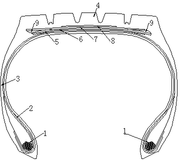
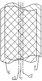
[0015] Example: such as figure 1 , 2 The shown directional steel belt pneumatic tire includes at least one pair of annular bead ring assemblies 1 arranged in parallel at the bead position, at least one layer of ply 2 wrapped around the bead rings, a belt reinforced with steel cords The belt layer assembly, the tread structure 4 with a pattern placed outside the belt layer assembly, and the sidewall 3 extending from the tread to the bead portion. The belt assembly is composed of at least two working belt layers 6, 7, at least one protective layer 8 and at most one transition layer 5. The steel cords of the belt layers 6 and 7 of the two working layers are arranged in opposite directions. The belt layers 6 and 7 of the two working layers are provided with insulating rubber parts 9 at the end points of both sides to reduce the shear stress at the end points of the belt layers during operation. The transverse centerline c1 and transverse centerline c2 of the belt layers 6 and 7...


PUM


Abstract

The invention discloses a directional steel wire belt type pneumatic tire structure. A novel belt structure design is adopted; belt steel wires are arranged on the outmost sides of a left tire shoulder and a right tire shoulder and are symmetric about the central surface of a tire crown. The directional steel wire belt type pneumatic tire structure is suitable for pneumatic tires adopting steel wire belts, which include car tires, truck and passenger car tires, engineering machinery tires and the like. The belt structure comprises at least two working layers, at least one protection layer and at least one transition layer.

Description

technical field [0001] The invention relates to the technical field of tire production. Background technique [0002] In steel belted pneumatic tires of ordinary structure, the widest working belt layer is usually located laterally and symmetrically on both sides of the centerline of the tire crown, resulting in the same wire direction at the edge of the outermost belt layer of the two shoulders. During the rolling process of the tire, the engine transmits the driving force to the rim, and the rim transmits the driving force to the bead, and the bead further transmits the driving force to the sidewall and tire shoulder, and the tire shoulder transmits the driving force to the belt layer and the tread , the final driving force is transmitted to the ground and the tires roll forward. When the driving force is transmitted from the shoulder to the crown, the force on both sides of the shoulder changes. The direction of the belt steel cords on one side is consistent with the dir...

Claims


Application Information

Patent Timeline
Patent Type & Authority Applications(China)
IPC IPC(8): B60C9/18
Inventor 王志平安登峰朱海涛裴权华陈建国谢红杰贾永军
Owner AEOLUS TIRE
Why Eureka
Try Eureka