
Combined water treatment impeller

A water treatment, combined technology, applied in the direction of water/sludge/sewage treatment, sustainable biological treatment, water aeration, etc. Problems such as inability to form at one time

Inactive Publication Date: 2014-06-04
上海蓝云水产科技发展有限公司
View PDF4 Cites 3 Cited by
  • Summary
  • Abstract
  • Description
  • Claims
  • Application Information

AI Technical Summary

Problems solved by technology

The existing water treatment impeller structure is only suitable for smaller water treatment equipment. Large water treatment processors are bulky, and the corresponding water treatment impeller is also relatively large. Such a large water treatment impeller cannot be formed at one time, so the existing water treatment impeller structure cannot be realized

Method used


Image

  • Combined water treatment impeller
  • Combined water treatment impeller
  • Combined water treatment impeller

Examples


Embodiment Construction

[0012] The present invention will be further described below in conjunction with the accompanying drawings and embodiments.

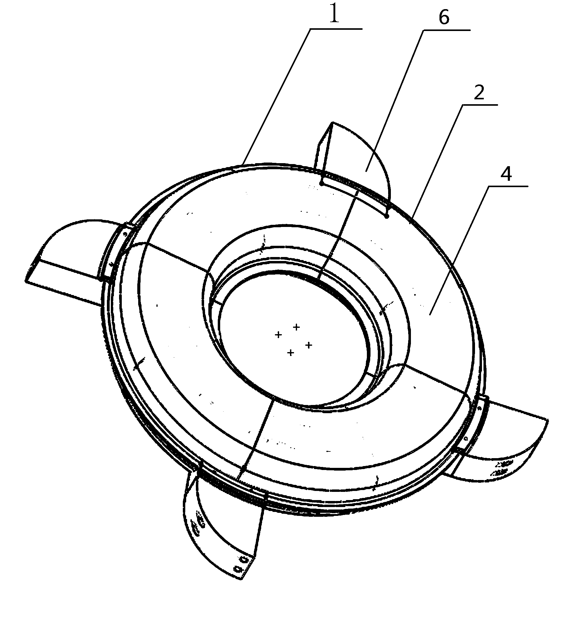
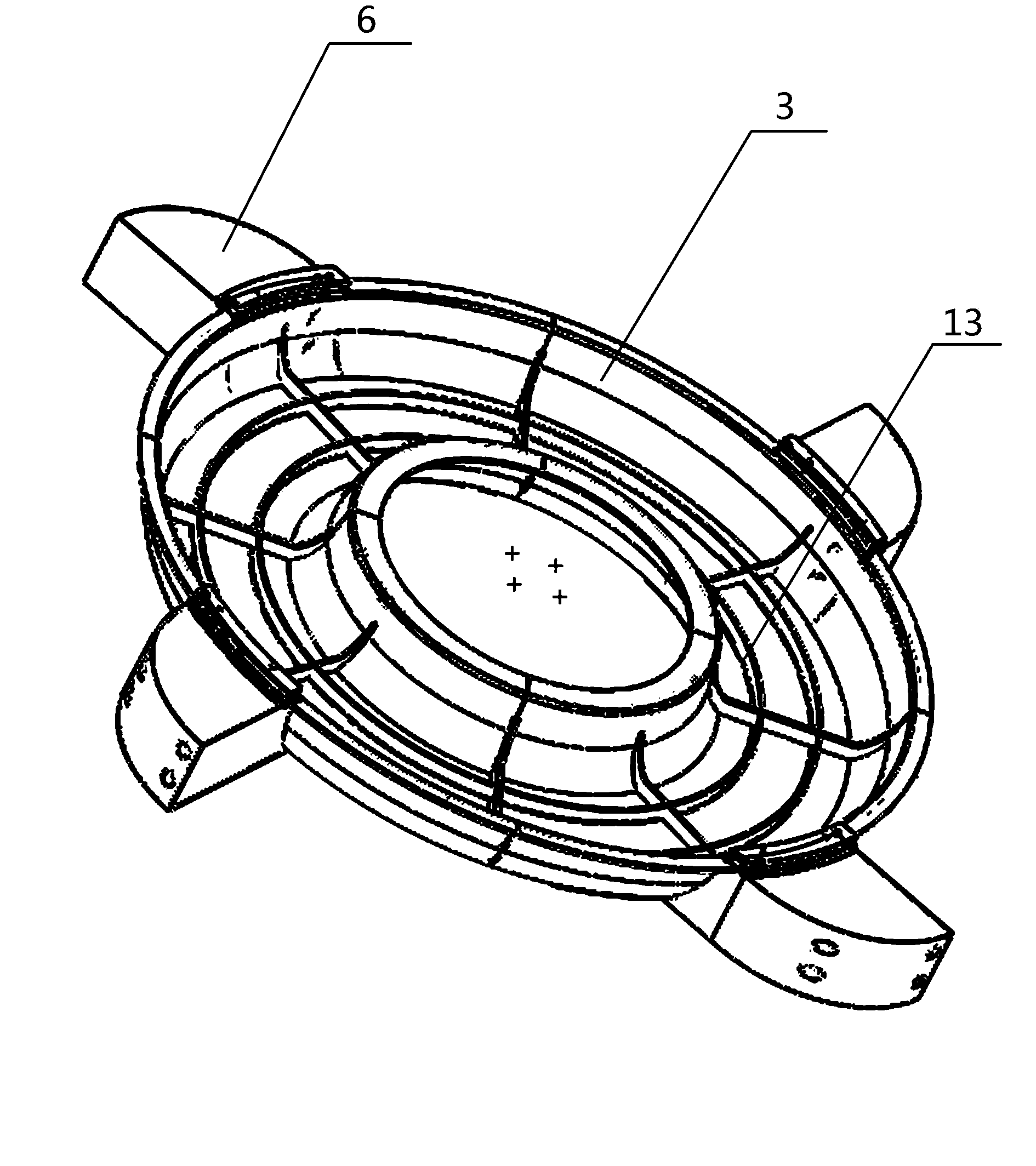
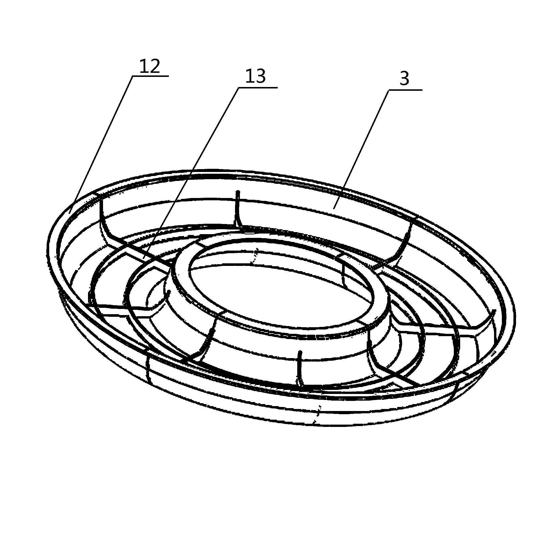
[0013] The invention discloses a combined water treatment impeller, which mainly includes an impeller body 1, which is different from the prior art in that: the impeller body 1 is in the shape of an annular body, and the inner cavity of the annular body is hollow, and the annular body is composed of The upper ring body 2 and the lower ring body 3 are spliced ​​up and down, and at least four blade bodies 6 are equidistantly distributed on the edge of the impeller body 1 . The inner cavity of the blade body 6 is hollow, which can effectively reduce the weight of the impeller body.

[0014] In a specific implementation, the upper ring body 2 is formed by splicing four upper circular arc pieces 4 to form a ring body, and the upper circular arc pieces 4 form a quarter circular arc body. The lower ring body 3 is formed by splicing four lower circular arc piec...


PUM


Abstract

The invention discloses a combined water treatment impeller. The combined water treatment impeller comprises an impeller body, wherein the impeller body is a ring body, an inner cavity of the ring body is hollow, the ring body is formed by splicing an upper ring body and a lower ring body in the vertical direction, at least four blade bodies are uniformly distributed on the edge of the impeller body at intervals, and an inner cavity of each blade body is hollow. By adopting a split-type assembled structure, the combined water treatment impeller is ingenious in concept, the splicing process is advanced, the assembled structure is accurate in positioning, and the inner cavity of the assembled large-sized water treatment impeller is hollow, so that a sufficient floating force can be provided, and the overall design of the product is reasonable; compared with the prior art, the combined water treatment impeller is more suitable for a large-sized water treatment device.

Description

technical field [0001] The invention relates to the technical field of water quality treatment equipment, in particular to a combined water treatment impeller, and in particular to its mechanical connection structure. Background technique [0002] Comparative document 1, patent number: ZL200320122566.9, patentee: Hu Haoxin, application date: 2003.12.15, this case discloses a "multi-hydraulic aerator impeller", including hollow inverted truncated conical wheel body, wheel The lower blade and the upper blade are evenly distributed on the side of the outer periphery, and the upper cover plate of the wheel body is provided with air suction holes. It is characterized in that one side of the upper blade is longitudinally installed with a blade that forms a certain angle with the blade surface of the upper blade. Smaller cotyledons. [0003] Comparative document 2, patent number: ZL 88214257.7, patentee: Shunde County No. The impeller type fish pond aerator impeller composed of a...

Claims


Application Information

Patent Timeline
Patent Type & Authority Applications(China)
IPC IPC(8): C02F7/00
CPCY02W10/10
Inventor 金茂飞
Owner 上海蓝云水产科技发展有限公司
Learn More