Withdrawing mechanism used during threading of sewing equipment

A sewing machine and threading technology, which is applied to sewing machine components, sewing machine protection devices, cloth feeding mechanisms, etc., can solve the difficulties of threading 15 and bottom stitching 16, block the threading operation, and fully meet the requirements of the garment manufacturing industry. Diverse needs and other issues

Active Publication Date: 2014-06-04
H S MASCH CO LTD
View PDF5 Cites 1 Cited by
  • Summary
  • Abstract
  • Description
  • Claims
  • Application Information

AI Technical Summary

Problems solved by technology

[0003] In addition, the thickness and weight of the elastic band material are different, these are important factors affecting the tension control, especially the thin and light elastic band material is not easy to control, often easy to cause either too loose or too tight, if Without a precise feeding device, it is difficult to fully meet the diverse needs of garment manufacturers
[0004] The known sewing machine 1 for sewing elastic bands is provided with a strip material feeding device 2 to provide a precise feeding device, but the problems it faces, such as figure 1 The sewing needle of this known sewing machine 1 shown in the drawing and the bottom stitching thread adjuster and the bottom sewing thread guide frame near the sewing needle are all shielded by the strip material feeding device 2, blocking the sewing thread 15 and the bottom sewing thread 16 The threading operation makes it very difficult to thread the suture 15 and the bottom suture 16, time-consuming and troublesome, and needs to be improved.

Method used


Image

  • Withdrawing mechanism used during threading of sewing equipment
  • Withdrawing mechanism used during threading of sewing equipment
  • Withdrawing mechanism used during threading of sewing equipment

Examples


Embodiment Construction

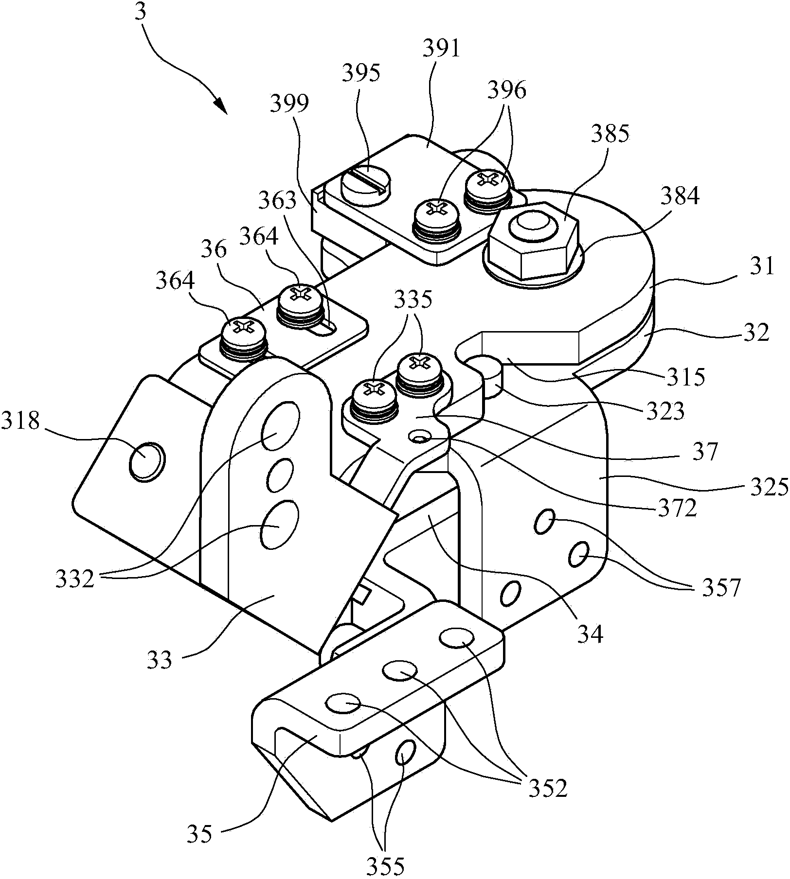
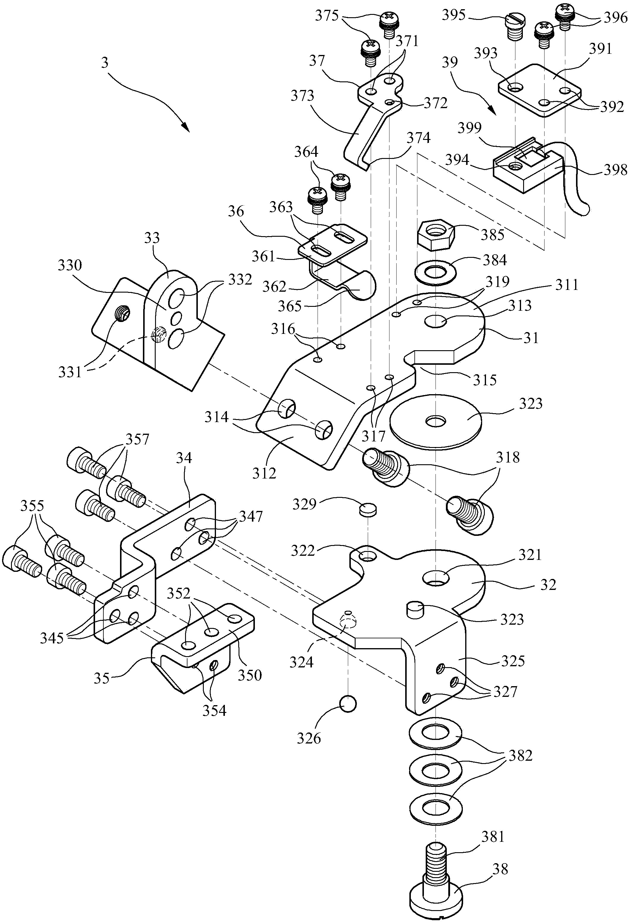
[0044] see Figure 2 to Figure 4 , Figure 6 Shown in, it is a preferred embodiment of the removal mechanism when the sewing equipment of the present invention is threaded. The quick removal mechanism 3 in this embodiment includes a base bracket 31, a steering bracket 32, a Bracket fixing part 33 , a zigzag connecting part 34 , a fixing part 35 , a spring clip 36 , a threading washer 37 , a pivot 38 and a safety switch 39 .

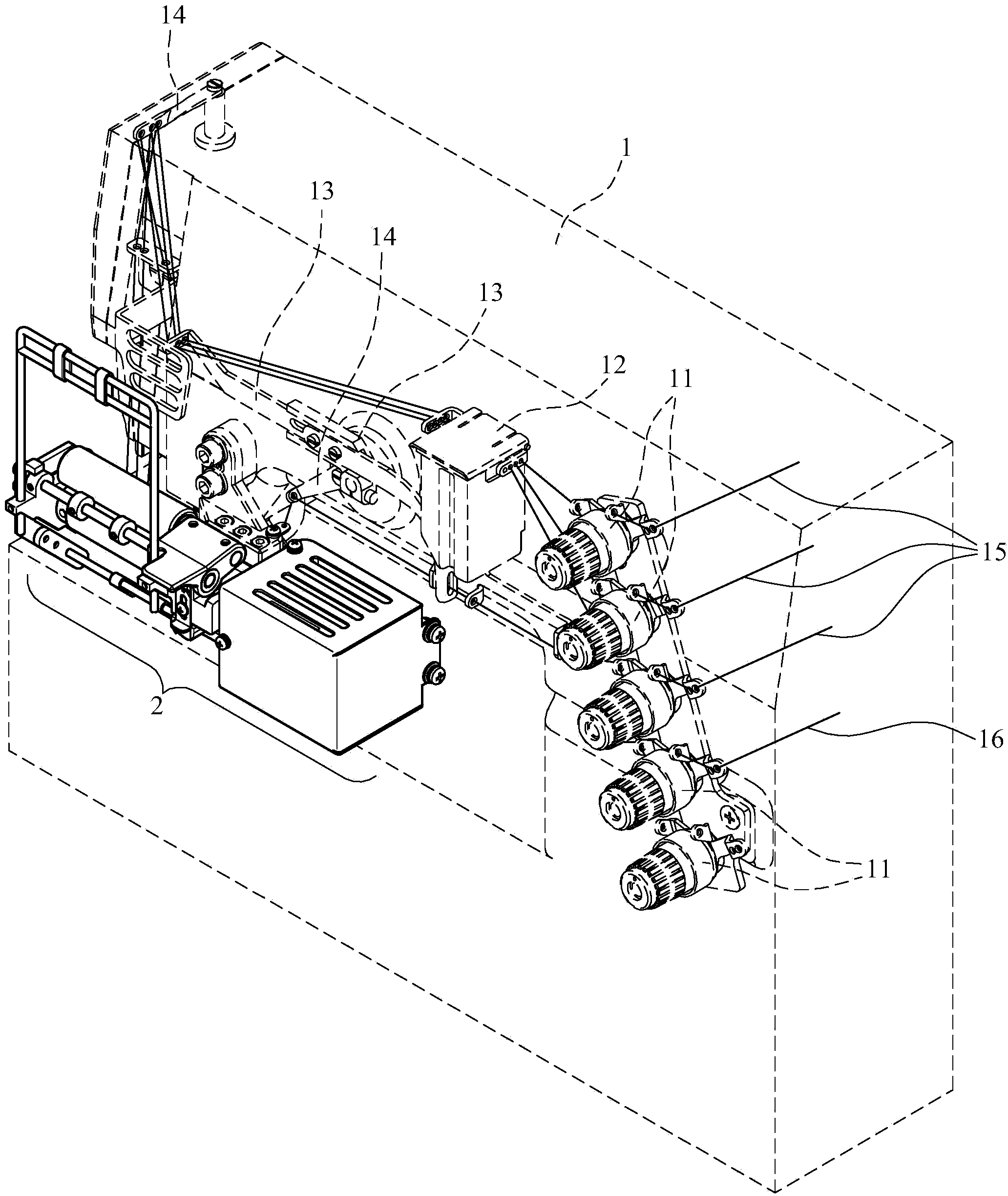
[0045] One end of the base bracket 31 is an arc-shaped end plate portion 311 , and the other end is a downwardly inclined inclined portion 312 . The end plate portion 311 is provided with a first shaft hole 313 for the pivot shaft 38 to pass through, and the inclined portion 312 is provided with a perforation 314 for locking the bracket fixing member 33 on the sewing machine 1 (such as Figure 10 shown in ).

[0046] One side of the base bracket 31 is provided with an oblique notch 315 and two screw holes 317 to lock the positioning column 323 of the s...


PUM


Abstract

The invention provides a withdrawing mechanism used during threading of sewing equipment. The withdrawing mechanism comprises a sewing machine, a band-shaped material feeding device and a quick withdrawing mechanism, wherein the quick withdrawing mechanism comprises a base support, a steering support, a supporting fixing piece, a bent connecting piece, a fixing piece and a pivot; the base support is fixedly provided with the support fixing piece so as to be fixed on the sewing machine; the steering support is pivotally arranged below the base support, and the bent connecting piece is fixed by the steering support; the fixing piece is fixedly arranged on the bent connecting piece; and the band-shaped material feeding device is fixed on the fixing piece, so that the band-shaped material feeding device can be withdrawn along with rotation of the steering support. During threading of a stitching thread and a bottom stitching thread, the steering support and the band-shaped material feeding device rotate so as to be withdrawn, open space is formed, and a stitching needle, a bottom stitching thread adjustor close to the stitching needle and a thread guiding rack close to the stitching needle are not stopped. During threading of the stitching thread and the bottom stitching thread, the withdrawing mechanism is simple, convenient, time-saving and easy.

Description

field of invention [0001] The present invention relates to a removing mechanism when sewing equipment is threaded; in particular, it relates to a sewing machine for sewing elastic ribbons with a ribbon feeding device. The strip material feeding device is removed to form an open space, so that the sewing needle and the bottom thread adjuster and wire frame near the sewing needle are not blocked, so it is simple and convenient when threading the suture and threading the bottom thread. Save time and trouble. Background technique [0002] According to the sewing machine for sewing the strip-shaped material of the elastic band, before the strip-shaped material is sewn on the clothing, the tension of the strip-shaped material must be delicately controlled, so that the strip-shaped material can be sewn on the clothing correctly according to the requirements. Typical example is as: when elastic band is sewed on underwear, often the required elastic force of different parts of the s...

Claims


Application Information

Patent Timeline
Patent Type & Authority Applications(China)
IPC IPC(8): D05B35/06D05B83/00D05B51/00
Inventor 李政育
Owner H S MASCH CO LTD
Why Eureka
Try Eureka