Ring permanent magnet assembly mechanism

An assembly mechanism and permanent magnet technology, applied in mechanical equipment, fixtures, etc., can solve problems such as damage to experimental materials, increased axial repulsion, operator injury, etc., to save time, simple and reliable structure, and increase the force arm. Effect

Active Publication Date: 2016-01-27
HARBIN INST OF TECH
View PDF6 Cites 0 Cited by
  • Summary
  • Abstract
  • Description
  • Claims
  • Application Information

AI Technical Summary

Problems solved by technology

[0002] Annular permanent magnet combinations are used in many fields such as traveling wave tubes and multi-stage cusp magnetic field plasma thrusters. In the process of assembling annular permanent magnets, there is repulsion between two sets of permanent magnet combinations with opposite polarities. As the two sets of permanent magnets keep approaching, this axial repulsion will continue to increase, and a slight vibration will easily transform into a tangential repulsion in the normal plane, which will eventually lead to eccentricity of the permanent magnet assembly during assembly.
During the assembly process of the ring-shaped permanent magnet with a strong magnetic field, because the permanent magnet is subjected to a large magnetic field force, a little carelessness may easily damage the experimental materials and cause injury to the operator

Method used


Image

  • Ring permanent magnet assembly mechanism
  • Ring permanent magnet assembly mechanism
  • Ring permanent magnet assembly mechanism

Examples


specific Embodiment approach 1

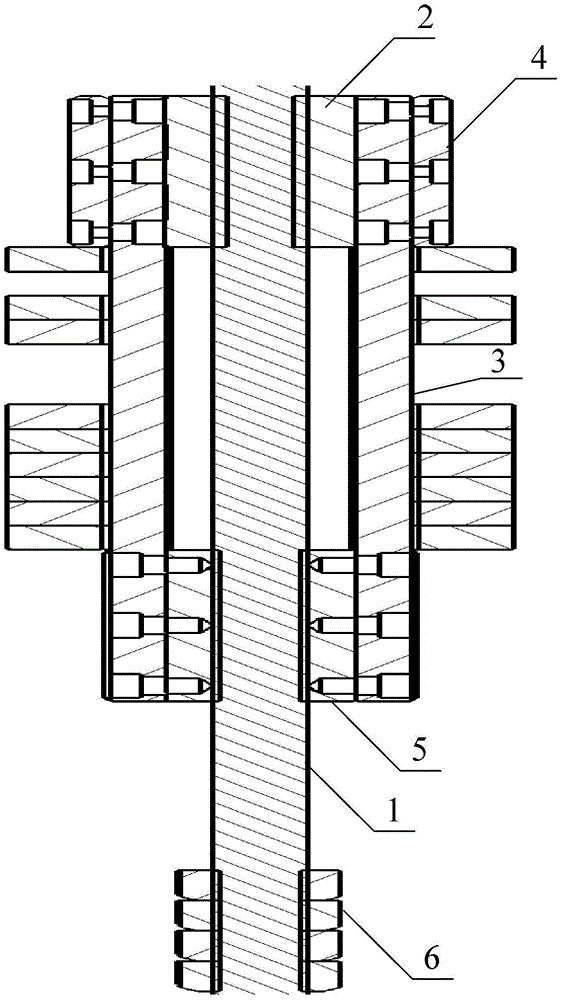
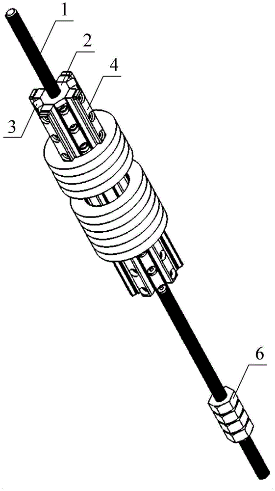
[0019] Specific implementation mode one: combine Figure 1 to Figure 8 To illustrate this embodiment, the annular permanent magnet assembly mechanism described in this embodiment includes a central long stud 1, a threaded sleeve combination, a through-hole sleeve combination and two sets of lock nuts 6;

[0020] The threaded sleeve combination includes a regular octagonal threaded sleeve 2, four equal-length ribs 3 and four metal buttons 4. The external thread of the stud 1 is engaged and connected, the rib 3 is a lath-shaped structure, the length of the rib 3 is twice the length of the regular octagonal threaded sleeve 2, and the width of the rib 3 is equal to the regular octagonal threaded sleeve 2. The side lengths of the sides are equal, and one end of the four ribs 3 is respectively fixed on four non-adjacent side walls of the regular octagonal threaded sleeve 2 by bolts, and the length direction of the four ribs 3 is in line with the regular octagonal thread The directi...

specific Embodiment approach 2

[0031] Specific implementation mode two: combination figure 1 , figure 2 and Figure 8 This embodiment is described. This embodiment is a further limitation of the annular permanent magnet assembly mechanism described in Embodiment 1. In this embodiment, each set of lock nuts 6 is composed of four nuts of the same size.

specific Embodiment approach 3

[0032] Specific implementation mode three: combination figure 1 and figure 2 Describe this embodiment. This embodiment is a further limitation of the annular permanent magnet assembly mechanism described in Embodiment 1. In this embodiment, the central long stud 1, the combination of threaded sleeves and the combination of through-hole sleeves are all Made of stainless steel material.


PUM


Abstract

The invention discloses an annular permanent magnet assembling mechanism, relates to a mechanical assembling mechanism and aims to solve the problem about eccentricity during reverse assembling of annular permanent magnets. The annular permanent magnet assembling mechanism comprises a regular octagonal threaded sleeve, a regular octagonal through hole sleeve and two groups of locknuts, the regular octagonal threaded sleeve, the regular octagonal through hole sleeve and the locknuts sleeve a central long screw column, four ribs combined with the threaded sleeve and four ribs combined with the through hole sleeve are crossly distributed, and the regular octagonal through hole sleeve is arranged between two groups of locknuts. By the aid of step action of transmission of the central long screw column, repulsion force stressed on permanent magnet combination during reverse assembling is overcome, the permanent magnet combination is kept close, and eccentricity of the permanent magnet combination during reverse assembling is avoided greatly by supporting of the central long screw column, the ribs and metal buttons. The annular permanent magnet assembling mechanism is applicable to assembling of the annular permanent magnets.

Description

technical field [0001] The invention relates to a mechanical assembly mechanism. Background technique [0002] Annular permanent magnet combinations are used in many fields such as traveling wave tubes and multi-stage cusp magnetic field plasma thrusters. In the process of assembling annular permanent magnets, there is repulsion between two sets of permanent magnet combinations with opposite polarities. As the two sets of permanent magnets keep approaching, this axial repulsion will continue to increase, and a slight vibration will easily transform into a tangential repulsion in the normal plane, which will eventually lead to eccentricity of the permanent magnet combination during the assembly process. During the assembly process of the ring-shaped permanent magnet with a strong magnetic field, because the permanent magnet is subjected to a large magnetic field force, a little carelessness is likely to damage the experimental materials and cause injury to the operator. In o...

Claims


Application Information

Patent Timeline
Patent Type & Authority Patents(China)
IPC IPC(8): F16B1/02
Inventor 马成毓刘辉孙国顺陈蓬勃赵隐剑于达仁
Owner HARBIN INST OF TECH
Why Eureka
Try Eureka