A Magnetic Ring Assembly Fixture for Terahertz Traveling Wave Tube Periodic Permanent Magnet System

A periodic permanent magnet and assembly fixture technology, which is applied in the direction of electrode system manufacturing, manufacturing tools, workpiece clamping devices, etc., can solve the problems of periodic permanent magnet system structure irregularity, inconvenient, laborious and time-consuming assembly process, etc., to achieve improved magnetic Ring assembly process, improve operability and convenience, and avoid safety risks and hidden dangers

Active Publication Date: 2021-02-19
INST OF APPLIED ELECTRONICS CHINA ACAD OF ENG PHYSICS
View PDF8 Cites 0 Cited by
  • Summary
  • Abstract
  • Description
  • Claims
  • Application Information

AI Technical Summary

Problems solved by technology

Due to the irregular structure, small size and limited space of the periodic permanent magnet system, most of the current magnetic ring assembly is manual direct assembly, which is inefficient and inconvenient
[0005] In the existing technology, when the magnetic ring is assembled, the whole magnetic ring is disassembled into two halves after magnetization, and the two halves of the magnetic ring are pressed into the gap between the pole shoes manually, and then the copper wire is wound on it and fixed, and the magnetic ring is fully charged. The axial magnetic induction intensity after magnetization is about 0.5T. To press two such strong magnetic field magnets together, it needs to overcome a very large magnetic field repulsion force. In addition, the thickness of the magnetic ring is only 2.5mm, and the pressing space is only enough for 2 fingers. It is also necessary to fix the copper wire with one hand. The whole assembly process is very laborious and time-consuming, and it is extremely inconvenient. During the assembly operation, the magnetic ring often flies out under the action of repulsion, which poses a safety hazard.

Method used


Image

  • A Magnetic Ring Assembly Fixture for Terahertz Traveling Wave Tube Periodic Permanent Magnet System
  • A Magnetic Ring Assembly Fixture for Terahertz Traveling Wave Tube Periodic Permanent Magnet System
  • A Magnetic Ring Assembly Fixture for Terahertz Traveling Wave Tube Periodic Permanent Magnet System

Examples


Embodiment 1

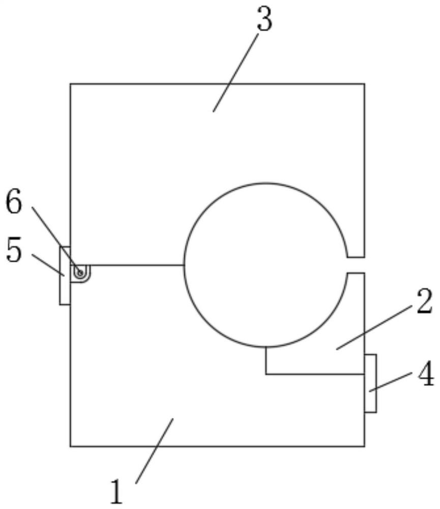
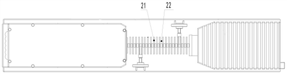
[0035] Such as figure 1 , image 3 , Figure 4 , Figure 5 , Figure 9 , Figure 10 , Figure 11 As shown, in this embodiment, a magnetic ring assembly fixture for a periodic permanent magnet system of a terahertz traveling wave tube includes a base 1 and a lower pole shoe arranged on the base 1 and cooperating with the pole shoe 21 of the terahertz traveling wave tube groove, the lower magnetic ring groove 102 arranged in the lower pole shoe groove and coaxial with the lower pole shoe groove, the lower copper wire groove 101 arranged in the lower magnetic ring groove 102 and coaxial with the lower magnetic ring groove 102, and the lower magnetic ring groove 101 arranged on the base The upper cover 3 on the upper cover 3, the upper pole shoe groove arranged on the upper cover 3 and cooperating with the pole shoe of the terahertz traveling wave tube, the upper magnetic ring arranged in the upper pole shoe groove and coaxial with the upper pole shoe groove The slot 302 and...

Embodiment 2

[0041] On the basis of the above embodiments, in this embodiment, the upper cover 3 is rotatably connected with the base 1 . In this way, the distance between the lower pole shoe and the upper pole shoe can be increased or decreased by the rotation of the upper cover 3 relative to the base 1, and the installation of the terahertz row is facilitated by increasing the distance between the lower pole shoe and the upper pole shoe. The wave tube facilitates the locking of the terahertz traveling wave tube by reducing the distance between the lower pole shoe slot and the upper pole shoe slot, and aligns the two semi-ring magnet blocks. The positional accuracy of the upper cover 3 and the base 1 can also be improved by rotating the upper cover 3 and the base 1 , and the upper cover 3 and the base 1 do not need to be positioned repeatedly during multiple uses, which is beneficial to improve the efficiency of assembly. In this embodiment, other contents not described are the same as th...

Embodiment 3

[0043] On the basis of the above embodiments, in this embodiment, the base 1 is provided with a base connection hole 104, and the upper cover 3 is provided with an upper cover connection hole 303 coaxial with the base connection hole 104. The upper cover connecting hole 303 and the base connecting hole 104 are rotatably equipped with a rotating shaft 6 . In this way, the upper cover 3 can be rotated relative to the base 1 with the rotating shaft 6 as the rotation center, so as to realize the relative rotation function of the upper cover 3 and the base 1 . In this embodiment, other contents not described are the same as those in the foregoing embodiments, so details are not repeated.


PUM


Abstract

The invention discloses a magnetic ring assembly fixture for a terahertz traveling wave tube periodic permanent magnet system, which comprises a base, a lower pole shoe groove arranged on the base, and a lower magnet arranged in the lower pole shoe groove and coaxial with the lower pole shoe groove The ring groove, the lower copper wire groove set in the lower magnetic ring groove and coaxial with the lower magnetic ring groove, the upper cover arranged on the base, the upper pole shoe groove arranged on the upper cover, and the upper pole shoe groove And coaxial with the upper pole shoe groove magnetic ring groove and the upper copper wire groove which is arranged in the upper magnetic ring groove and coaxially arranged with the upper magnetic ring groove. The beneficial effects of the present invention are: the present invention can improve the positioning accuracy of the half-ring magnetic block, and is beneficial to overcome the repulsive force of the half-ring magnetic block, significantly improves the assembly process of the magnetic ring, and improves the operability and convenience of assembly , reduces the difficulty of assembly, saves manpower and time, improves the efficiency of the TWT magnetic ring assembly process, and effectively avoids safety risks and hidden dangers in the assembly process.

Description

technical field [0001] The invention relates to the technical field of magnetic ring assembly, in particular to a magnetic ring assembly fixture for a periodic permanent magnet system of a terahertz traveling wave tube. Background technique [0002] With the development of information technology and the explosive growth of information transmission, the original spectrum resources are becoming more and more difficult to meet the needs of our growing information development. In this case, people focus on higher frequency spectrum resources Above, terahertz (THz) waves came into being. Terahertz is the unit of frequency. According to customary definitions, electromagnetic waves with frequencies in the range of 0.1-10THz (wavelength 0.03-3mm) are generally referred to as terahertz waves. Due to the narrow beam, good directivity, strong anti-interference ability, strong penetrating power and no ionizing radiation, the terahertz beam has great potential in the fields of material ...

Claims


Application Information

Patent Timeline
Patent Type & Authority Patents(China)
IPC IPC(8): B25B11/02H01J9/00
Inventor 黄银虎雷文强胡鹏蒋艺马乔生宋睿曾造金陈洪斌
Owner INST OF APPLIED ELECTRONICS CHINA ACAD OF ENG PHYSICS
Why Eureka
Try Eureka