a hydraulic clutch

A technology of hydraulic clutch and pressure oil, applied in the field of clutch, can solve the problems of difficult processing, high manufacturing cost, and damage to the inner wall of the stator, etc., and achieves the effects of high switching reliability, low manufacturing cost and easy processing.

Active Publication Date: 2016-06-15
胡阳
View PDF13 Cites 0 Cited by
  • Summary
  • Abstract
  • Description
  • Claims
  • Application Information

AI Technical Summary

Problems solved by technology

The disclosed technology realizes the disengagement and closing of the hydraulic clutch through the vane structure, inherits the advantages of the traditional hydraulic clutch, and also has the advantages of large load, low noise, and convenient manipulation. However, it uses a rotor, a stator, and vanes sliding on the stator. When rotating, under the action of centrifugal force and pressure oil, the tip of the blade clings to the inner surface of the stator. There are some disadvantages in this structure. For example, the precision of the curved surface of the inner cavity of the stator is high, which makes the processing difficult and the manufacturing cost high; multiple The cams are coaxial, and the structure of each cam and the inner circumference of the stator is more difficult to manufacture and assemble, and the rotational torque of each cam is transmitted to the same shaft during high-speed rotation, which is easy to interfere with each other, usually causing rotation Unstable or biting the inner wall of the stator or the outer circle of the rotor

Method used


Image

  • a hydraulic clutch
  • a hydraulic clutch
  • a hydraulic clutch

Examples


Embodiment

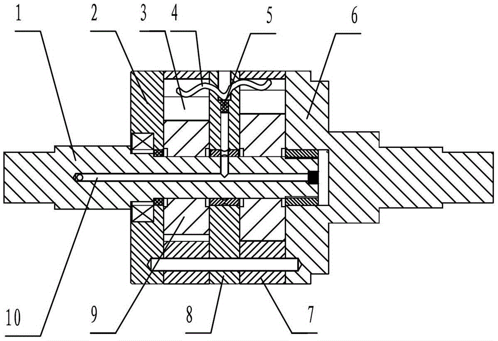
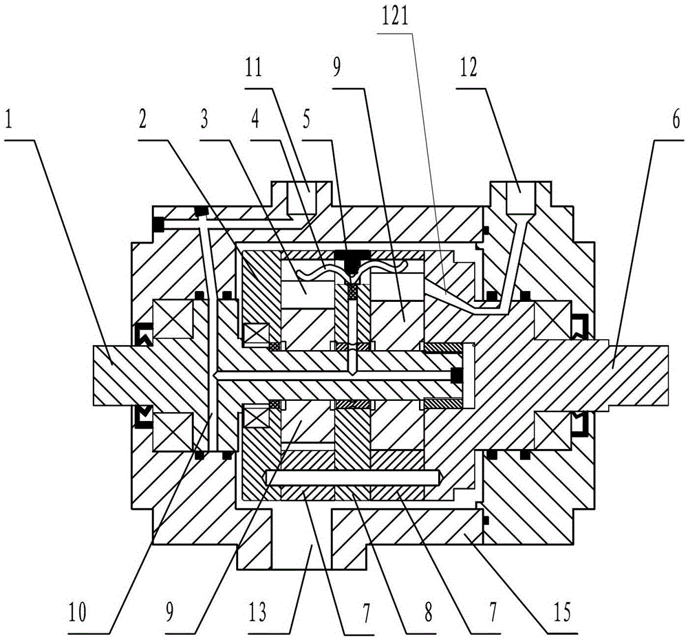
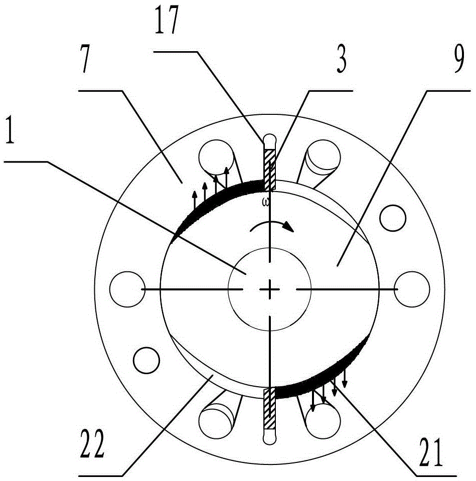
[0021] Embodiment: a hydraulic clutch of the present invention, as attached figure 1 , attached figure 2 , attached image 3 As shown, it includes an input shaft 1 and an output shaft 6 arranged coaxially, and one or more cam-type rotors 9 are arranged on the input shaft 1. Correspondingly, one or more swivel rings 7 are arranged on the output shaft 6. A preferred solution is that each rotor 9 corresponds to one swivel ring 7; the swivel ring 7 has a circular inner cavity, and the rotor 9 is accommodated in the inner cavity.

[0022] A plurality of slots 17 are radially provided on the circumferential wall of the inner cavity of the swivel ring 7, and the vanes 3 are slidably arranged in the slots 17. The root of 3 protrudes out of the slot 17 against the outer peripheral surface of the rotor 9; the cross section of the rotor 9 includes a circular arc segment and a curved segment, and the circular arc segment of the rotor 9 forms a clearance fit with the inner cavity of the...


PUM


Abstract

The invention relates to a hydraulic clutch which comprises an input shaft and an output shaft. The input shaft and the output shaft are coaxially arranged. The input shaft is provided with one or more cam type rotors. The output shaft is provided with one or more rotating rings. The rotating rings are provided with round inner cavities. The rotors are contained in the inner cavities. The circumferential walls of the inner cavities of the rotating rings are provided with a plurality of slots in the radial direction. Blades are arranged in the slots in a sliding mode. The top ends of the blades are affected by external elastic force or hydraulic force or combination of the external elastic force and the hydraulic force, so that the root portions of the blades extend out of the slots and abut against the peripheral faces of the rotors. The section of each rotor comprises an arc section and a curved section, and the arc sections of the rotors and the inner cavities of the rotating rings are in clearance fit. The peripheral faces of the curved sections of the rotors and the walls of the inner cavities of the rotating rings can surround two cavities on the two sides of each blade. One cavity is a suction cavity communicated with an external air inlet channel, and the other cavity is a pressure cavity communicated with an air outlet channel. According to the hydraulic clutch, closing and separating motions of the clutch can be more stable and higher in reliability.

Description

technical field [0001] The present invention relates to a clutch, in particular to a hydraulic clutch. Background technique [0002] In the transmission chain, especially in the transmission chain between shafts, the traditional hydraulic clutch that separates and closes by hydraulic drive is used between the driving part and the driven part. Compared with other traditional clutches, it has the advantages of less heat generation and transmission efficiency. High and stable, not easy to fail, service life and other effects; Therefore, an inventor proposed a title called "a kind of overrunning clutch" (publication number: CN101660576 public technology), which includes an inner rotor, which is axially arranged on the inner rotor. There are a plurality of radially retractable blades; an outer rotor, the inner rotor is located in the outer rotor and the outer surface of the inner rotor and the inner surface of the outer rotor define a first cavity and a second cavity isolated fro...

Claims


Application Information

Patent Timeline
Patent Type & Authority Patents(China)
IPC IPC(8): F16D33/00
Inventor 胡凯王新彪陈伟娟胡阳
Owner 胡阳
Why Eureka
Try Eureka