

Vibration reduction method and vibration reduction system
A vibration damping system and output shaft technology, which is applied in portable mobile devices, inertial force compensation, manufacturing tools, etc., can solve problems such as numb hands, unfavorable use of users, and harmful user hand health, etc., and achieve the effect of strong practicability.
- Summary
- Abstract
- Description
- Claims
- Application Information
AI Technical Summary
Problems solved by technology
Method used
Image

Examples
Embodiment Construction
[0042] The present invention will be described in detail below in conjunction with specific embodiments shown in the accompanying drawings. However, these embodiments do not limit the present invention, and any structural, method, or functional changes made by those skilled in the art according to these embodiments are included in the protection scope of the present invention.
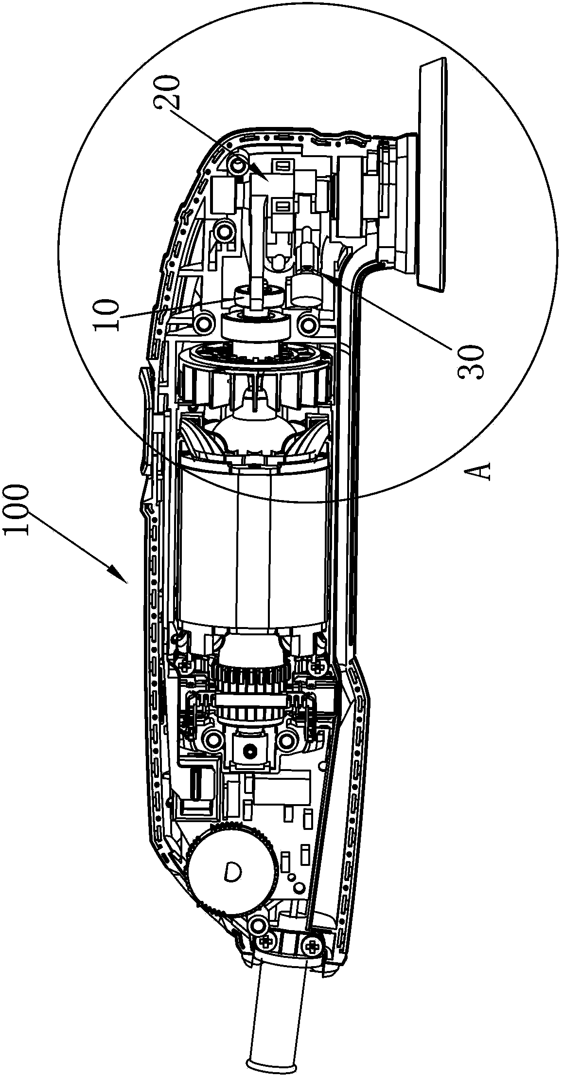
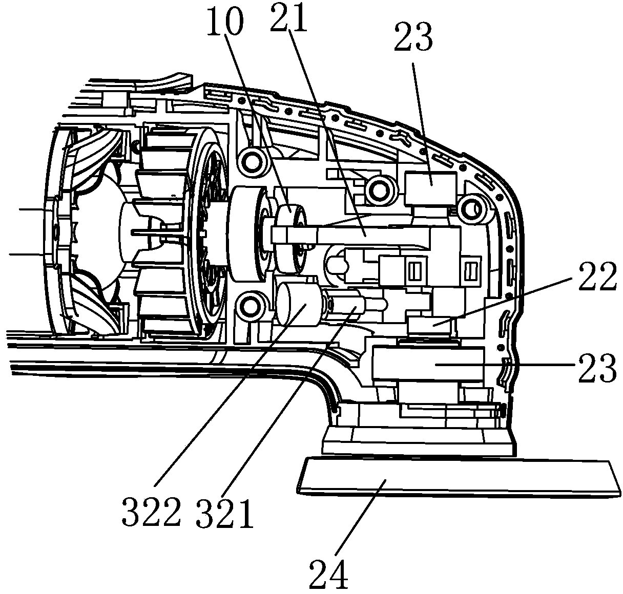
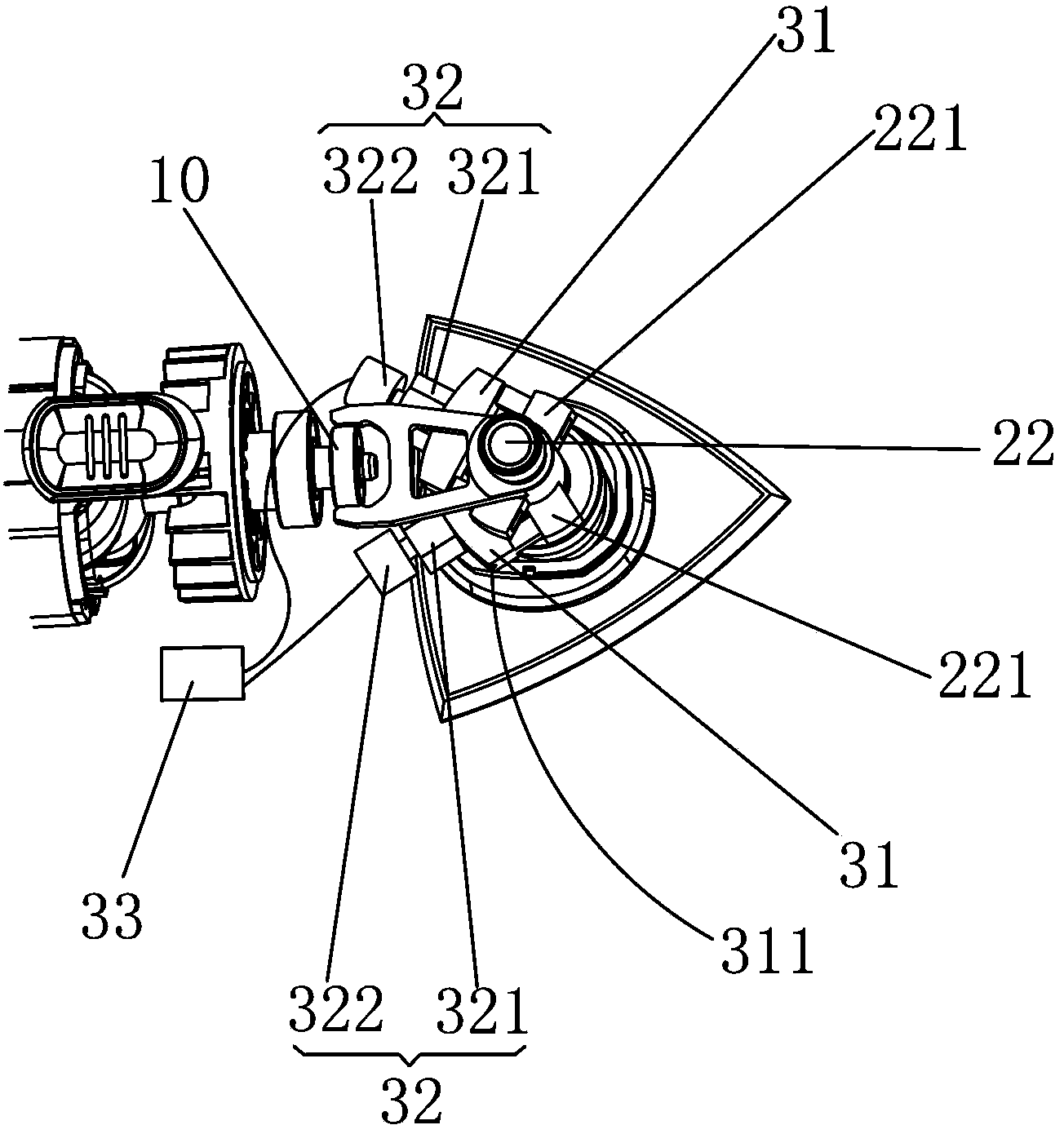
[0043] ginseng Figure 1 to Figure 5 As shown, in an embodiment of the present invention, the multifunctional machine 100 with the vibration damping system 30 includes an eccentric member 10, a shift fork 21, an output shaft 22 fixedly connected to the shift fork 21, and a shaft sheathed on the periphery of the output shaft 22 Cover 23, and the working head 24 that is connected to output shaft 22 free ends. The multifunctional machine 100 includes a motor, which drives the eccentric member 10 to rotate eccentrically, and the eccentric member 10 drives the shift fork 21 and the output shaft 22 to recip...
PUM
 Abstract
Description
Claims
Application Information