Structure and realization method of an anti-suckback self-radiating lamp

A self-dissipating and anti-suckback technology, which is applied in lighting and heating equipment, air-proof/waterproof devices, cooling/heating devices of lighting devices, etc. Simultaneous compliance issues

Active Publication Date: 2015-12-30
苏州盛泽科技创业园发展有限公司
View PDF5 Cites 0 Cited by
  • Summary
  • Abstract
  • Description
  • Claims
  • Application Information

AI Technical Summary

Problems solved by technology

[0002] In the field of lighting, indoor and outdoor sealed lighting fixtures cannot balance the moisture-proof and heat dissipation. Absolute sealing and moisture-proof can be done, but the heat dissipation cannot meet the needs, and vice versa.
Since the above two important technical indicators cannot meet the standards at the same time, all sealed lighting fixtures fail or are damaged beyond the design life cycle and cannot be repaired.
The main reason is that due to the aging of the seals of the lamps, the structure of the lamp shell is sparse and the density is different due to cost factors, and because the current general sealed lighting lamps do not have any filler in the lamp housing, the sealed lamps are due to the environmental temperature. Changes and when the light source and electrical appliances are turned on or off, there will be random positive and negative pressure alternating states in the lamp housing. The air will be sucked back into the shell of the sealed lighting fixture, and the moisture in the air will gather in the shell of the lamp to form condensed water that will corrode the light source and electrical appliances in the lamp. In addition, because of the waterproof requirement, there is usually no way to guarantee the heat dissipation requirements of the light source and electrical appliances of the luminaire.

Method used


Image

  • Structure and realization method of an anti-suckback self-radiating lamp
  • Structure and realization method of an anti-suckback self-radiating lamp
  • Structure and realization method of an anti-suckback self-radiating lamp

Examples


Embodiment Construction

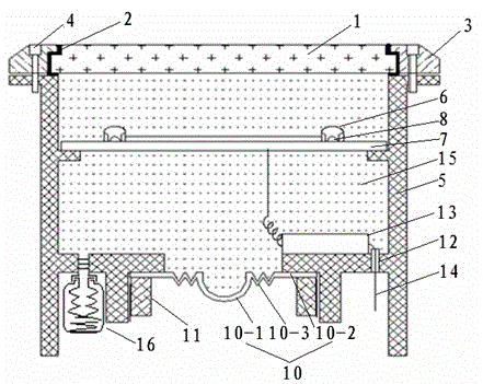
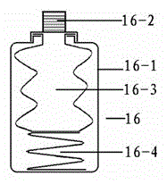
[0018] Such as Figure 1 to Figure 7 As shown, an anti-reflective self-radiating lamp structure includes sealed tempered glass 1, sealed tempered glass rubber part 2, tempered glass metal cover 3, lamp shell 5, light source lens or reflector 6 and LED light source installed Or the control circuit board 7 and the light source driver 13 of the lamp 8 of the traditional light source, and also include the insulating heat-conducting oil expansion rubber part 10, the insulating heat-conducting oil expansion rubber part locking the outer wire lock nut 11, the wire-passing sealing lock nut 12, the insulating heat-conducting oil 15. An oil tank 16 attached to the expansion of insulating heat-conducting oil.

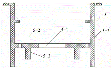
[0019] A middle hole 5-1 and two screw holes 5-2 are respectively provided on the inner bottom surface of the cavity of the lamp housing 5, and a ring of protrusions 5-3 with internal threads are arranged on the outer bottom surface of the cavity.

[0020] The insulating and heat...


PUM


Abstract

The invention relates to a self-heat-dissipating type lamp structure preventing sucking back and an achieving method. An auxiliary insulation conduction oil expansion fuel tank and a wire passing seal locking nut are connected to two screw holes in a screwed mode respectively. A power wire connected with a light source driver is connected with power through the wire passing seal locking nut. An insulation conduction oil expansion rubber piece is fixed into a circle of protrusions with internal threads by a locking external thread locking nut of the insulation conduction oil expansion rubber piece so that a middle hole can be sealed. Electrical light source devices are immerged into insulation conduction oil. Air in a lamp body is emptied so that the interior of a cavity of a shell of a lamp can be in a normal pressure state or in a micro positive pressure state due to environmental temperature change and turning on or off of the light source, the phenomenon of air sucking back caused by aging of a sealing piece of the lamp or the poor structural quality of the shell of the lamp due to manufacturing factors or the difference of the density or the temperature difference is effectively avoided, humidity and accumulated water are prevented from entering the shell of the lamp, the moisture-proof problem generally existing in the sealing type illuminating lamp is solved, the insulation conduction oil can transfer heat to the exterior of the lamp body fast and uniformly, and the heat dissipation problem is solved.

Description

technical field [0001] The present invention relates to a lamp structure in the field of lighting, in particular to an anti-suckback self-radiating lamp structure and its implementation method, which are generally used in indoor and outdoor sealed lighting lamps, such as buried lamps, spotlight lamps, and linear wall washers. Lamps with LED light source and traditional light source. Background technique [0002] In the field of lighting, the moisture-proof and heat-dissipation of indoor and outdoor sealed lighting fixtures cannot be well balanced. Absolute sealing and moisture-proof can be done, but the heat dissipation cannot meet the needs, and vice versa. Since the above two important technical indicators cannot meet the standards at the same time, all sealed lighting fixtures fail or are damaged beyond the design life cycle and cannot be repaired. The main reason is that due to the aging of the seals of the lamps, the structure of the lamp shell is sparse and the densit...

Claims


Application Information

Patent Timeline
Patent Type & Authority Patents(China)
IPC IPC(8): F21S8/00F21V29/85F21V31/04F21Y101/02F21V29/58F21Y115/10
Inventor 王蓓徐海通
Owner 苏州盛泽科技创业园发展有限公司
Why Eureka
Try Eureka