Eureka AIR delivers breakthrough ideas for toughest innovation challenges, trusted by R&D personnel around the world.

Replaceable shear-resistant energy consumption device for high-speed railway hollow swing pier

An energy-dissipating device and high-speed railway technology, applied in the direction of bridges, bridge construction, bridge parts, etc., can solve the problem of the limited shear capacity of the pier body of the hollow pier, high requirements for the shear resistance of the pier body, and large energy-dissipating devices of the hollow pier and other problems to achieve the effect of solving the insufficient space for disassembly and installation, avoiding external environmental erosion, and overcoming the small space for installation and disassembly

Active Publication Date: 2022-04-26
CENT SOUTH UNIV
View PDF7 Cites 0 Cited by
  • Summary
  • Abstract
  • Description
  • Claims
  • Application Information

AI Technical Summary

Problems solved by technology

However, the external energy-consuming components are easily eroded by the external environment (such as rainwater, mudslides, rockfall impacts, etc.), and the service life will be greatly shortened.
[0003] High-speed railway piers are generally gravity piers, which have high requirements for the shear resistance of the piers, while hollow piers have relatively limited shear resistance. The existing swing piers The energy-dissipating structure at the bottom of the pier cannot provide additional shear capacity for the pier body
[0004]The energy dissipation device of the existing swinging pier system is mainly installed at the lift-off interface at the bottom of the pier, and the position of the swinging interface at the bottom of the pier is more complicated and concentrated The problem is that under the action of strong earthquakes, it is easy to cause damage to the bottom of the pier
[0005] Hollow bridge piers generally require larger energy-dissipating devices, and too large energy-dissipating devices will greatly increase the probability of damage, and the space for installation and disassembly is limited

Method used


Image

  • Replaceable shear-resistant energy consumption device for high-speed railway hollow swing pier
  • Replaceable shear-resistant energy consumption device for high-speed railway hollow swing pier
  • Replaceable shear-resistant energy consumption device for high-speed railway hollow swing pier

Examples


Embodiment Construction

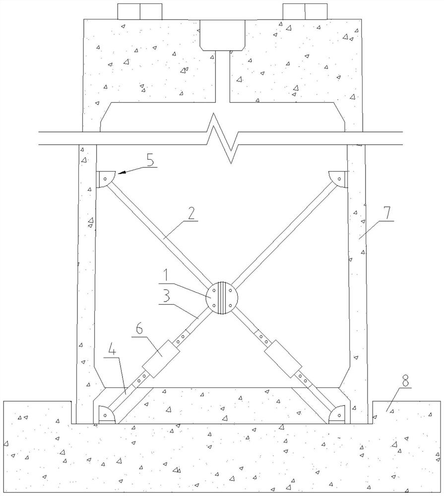
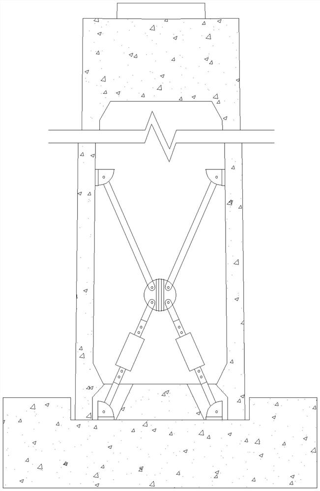
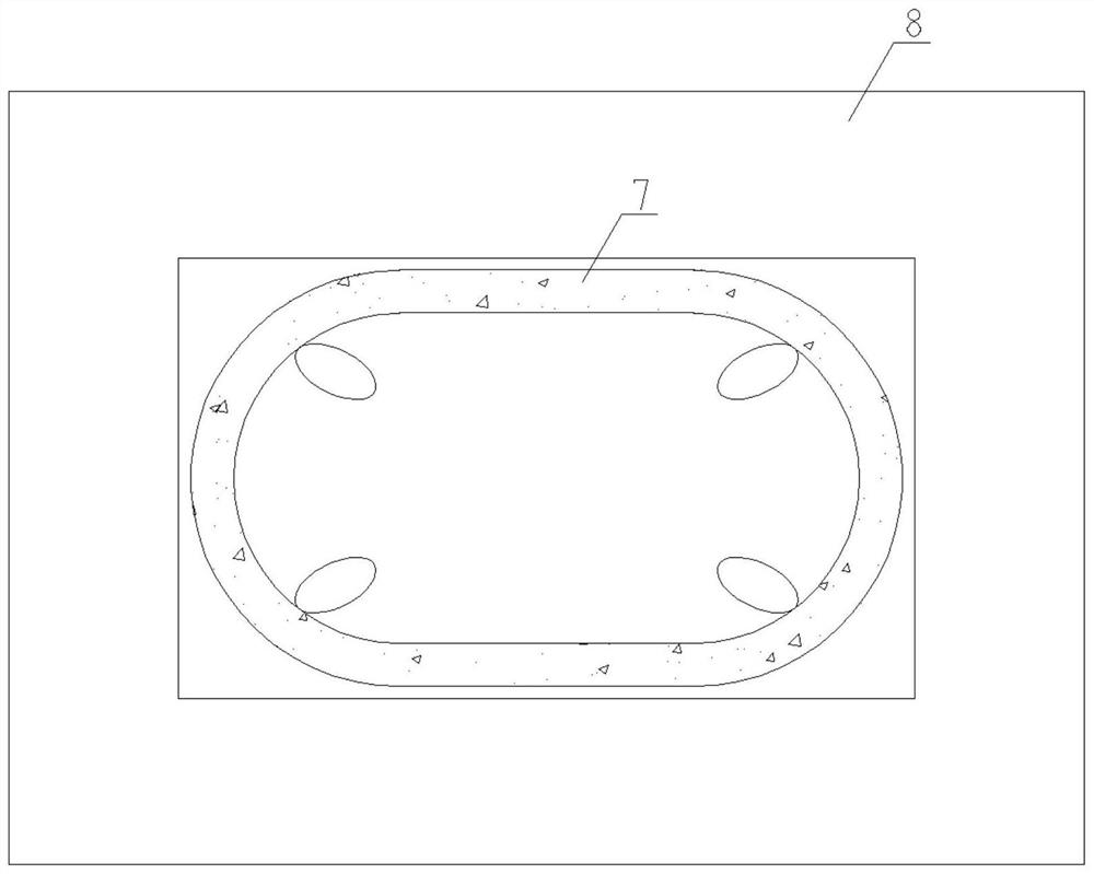
[0020] Such as Figure 1 to Figure 5 As shown, the replaceable shear energy-dissipating device disclosed in this embodiment for the high-speed railway hollow swing pier includes a diagonal brace and an energy-dissipating member.

[0021] The oblique brace frame of this embodiment includes a hinged seat 1, an upper oblique rod 2, an upper section 3 of the lower oblique rod, a lower section 4 of the lower oblique rod, and a mounting base 5. There are four upper oblique rods 2 and an upper section 3 of the lower oblique rod. There are four respectively in the lower section 4 of the down-slope bar, and an energy-dissipating member 6 is respectively connected between them.

[0022] The hinge seat 1 is two pairs of lug plates welded and formed in a cross-shaped staggered arrangement, and oblique rod installation holes are respectively provided outside the intersecting area of ​​each pair of lug plates.

[0023] The mounting base 5 includes a backing plate 51 and a double ear plate ...


PUM


Abstract

The invention discloses a replaceable shear-resistant energy consumption device for a high-speed railway hollow swing pier, which is detachably mounted in an inner cavity of the hollow pier, and a plurality of energy consumption components are arranged at the bottom of the inner cavity of the hollow pier in an inclined strut manner, so that the shear-resistant capability of a pier body of the hollow pier can be ensured, and the shear-resistant capability of the pier body of the hollow pier can be improved. The problems that a traditional swing pier bottom energy dissipation device is insufficient in disassembly and installation space, the service life is affected due to environmental erosion when the energy dissipation device is arranged outside the pier bottom and the pier bottom is stressed in a concentrated mode can be solved, and the pier bottom stress area is effectively enlarged. And energy consumption accumulation can be achieved through the arrangement of the multiple dispersion energy consumption components, and the large damage probability caused by the fact that a large energy consumption device is arranged on the hollow pier can be avoided. Under normal use and frequent earthquakes, the pier does not have lift-off swing of a pier bottom interface, and the stress of the pier is the same as that of a traditional pier; under the action of design earthquakes and rare earthquakes, lift-off swing of a pier bottom interface of the pier occurs, and earthquake energy is dissipated through pier body swing and pier bottom energy dissipation components.

Description

technical field [0001] The invention belongs to the field of vibration reduction and isolation of bridge engineering, in particular to a replaceable anti-shear energy consumption device for hollow swing pier of high-speed railway. Background technique [0002] At present, the application and research of swinging piers are mainly concentrated in highway bridges, and there are few related researches on high-speed railway piers. Swing bridge piers have excellent seismic isolation and post-earthquake self-resetting capabilities. As the main energy-dissipating components of swinging bridge piers, energy-dissipating components should be easy to replace. Therefore, energy-dissipating components are mostly arranged outside the pier body for easy replacement. However, the external energy-consuming components are easily eroded by the external environment (such as rainwater, mudslides, rockfall impacts, etc.), and the service life will be greatly shortened. [0003] High-speed railway...

Claims


Application Information

Patent Timeline
Patent Type & Authority Applications(China)
IPC IPC(8): E01D19/00E01D19/02
CPCE01D19/00E01D19/02Y02A30/30
Inventor 蒋丽忠聂磊鑫周旺保彭东航左勇健王晓婵娟任振彬蒋智勇付豪
Owner CENT SOUTH UNIV
Why Eureka
Eureka Blog
Learn More