

Trolley sealing device
A technology of sealing device and trolley, which is applied in the direction of engine sealing, furnace type, furnace, etc., to achieve good sealing effect, ensure sealing effect and reduce wear
- Summary
- Abstract
- Description
- Claims
- Application Information
AI Technical Summary
Problems solved by technology
Method used
Image

Examples
Embodiment Construction
[0015] Preferred embodiments of the present invention will be described in detail below in conjunction with the accompanying drawings.
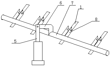
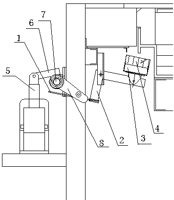
[0016] Such as figure 1 and figure 2 As shown, this embodiment provides a trolley sealing device, including a sealing component and a power component, and the sealing component includes a spring steel plate 1, a rotating member 1, a sealing plate 3 and fiber cotton 4, and the fiber cotton 4 is fixed on On the sealing plate 3, the sealing plate 3 is connected to one end of the rotating member 2, and the other end of the rotating member 2 is connected to the spring steel plate 1, and the rotating member 2 is in an 'L' shape. The corners of the first rotating part 2 are movably connected to the furnace body. The power components include an electric push rod 5, a second rotating part 6, a main shaft 7 and a pusher 8 for moving the sealing parts to seal. The second rotating part 6 It is an 'L' shape, one end of the rotating part 6 is connected ...
PUM
 Abstract
Description
Claims
Application Information