
Visible sampling method for fracture network in surrounding rock

A technology of fissure network and surrounding rock, applied in sampling devices and other directions, can solve the problems such as the description of the internal fissures of the surrounding rock, the lack of a clear understanding of the real state of the surrounding rock, and the inability to reproduce the fissure network of the surrounding rock. The effect of secondary damage and simple on-site operation

Inactive Publication Date: 2014-06-04
POWERCHINA HUADONG ENG COPORATION LTD
View PDF3 Cites 10 Cited by
  • Summary
  • Abstract
  • Description
  • Claims
  • Application Information

AI Technical Summary

Problems solved by technology

During the construction of URL in Canada, the damage evolution process of surrounding rock excavation was systematically studied in several test sites. The surrounding rock damage was evaluated by various methods, such as the half-porosity of residual blast holes after drilling and blasting excavation, The description of visible crack shape and quantity, visible failure shape, wave velocity change, groundwater permeability change, gas permeability change, acoustic emission test, etc., combined these results have a relatively comprehensive understanding of the surrounding rock damage evolution process under the specific conditions of the URL, However, none of these technical means can directly describe the internal fracture characteristics of the surrounding rock, and there is no intuitive understanding of the fracture network of the surrounding rock. The fundamental reason is that during the sampling process, new cracks are generated in the surrounding rock due to the excavation and unloading effect. Or cake, it is impossible to truly reproduce the fissure network inside the surrounding rock, and there is no clear understanding of the real state inside the surrounding rock

Method used


Image

  • Visible sampling method for fracture network in surrounding rock

Examples


Embodiment Construction

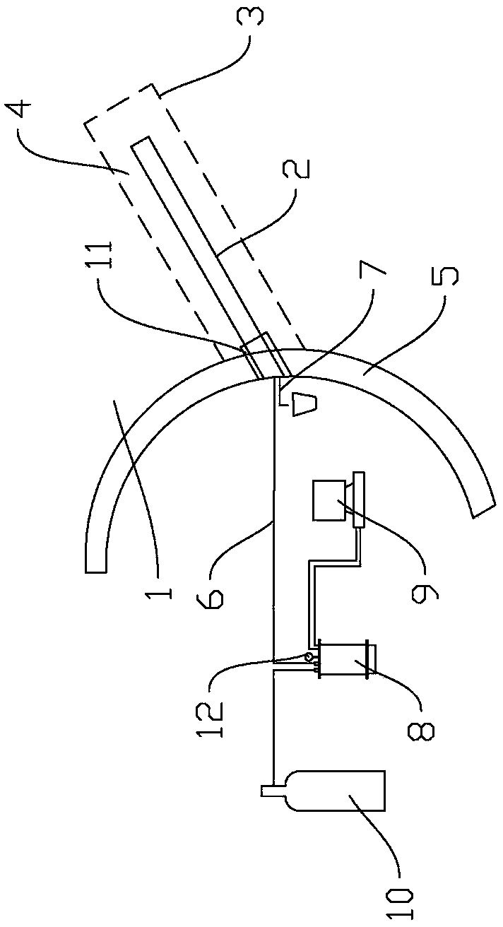
[0018] Such as figure 1 As shown, in this embodiment, a lining 5 is built close to the surrounding rock 1, and a perfusion hole 2 is drilled in the excavation damage area of ​​the surrounding rock. The perfusion hole 2 penetrates the lining, and a packer is set at the opening of the perfusion hole 2 11. The perfusion hole 2 is built with a perfusion pipe 6 and a grout return pipe 7, wherein one end of the perfusion pipe 6 passes through the lining 5 and ensures 10 cm of intrusion into the rock, and the other end passes through the packer 11 to connect to the perfusion container 8, which is connected to nitrogen One end of the tank 10 ; one end of the grout return pipe 7 is located in the pouring hole 2 , and the other end passes through the packer 11 and is placed outside the lining 5 . In this example, the perfusion container 8 is connected with a computer 9 for data collection and a pressure gauge 12 for monitoring the pressure of the container.

[0019] The main function o...


PUM

PropertyMeasurementUnit
Tensile strengthaaaaaaaaaa
Apertureaaaaaaaaaa
Hole depthaaaaaaaaaa

Abstract

The invention relates to a visible sampling method for a fracture network in a surrounding rock, which is simple to operate, and low in cost, effectively avoids secondary damage to the rock core in coring by drilling a hole, and guarantees the real and complete fracture network of the rock core in the damaged area. The technical scheme of the method is as follows: a lining is built close to the surrounding rock, a pouring hole is drilled in the damaged area to be excavated of the surrounding rock, the pouring hole is characterized in that a packer is arranged at the mouth, the pouring hole is internally provided with a pouring tube and a slurry return pipe, which penetrate through the packer, one end of the pouring tube needs to penetrate through the lining and goes into the rock by 10cm, the other end of the pouring tube is connected with a pouring vessel which is communicated with a nitrogen tank, and is connected with a computer for data acquisition and a pressure gage for monitoring the pressure of the vessel. The method is applicable to underground engineering field.

Description

technical field [0001] The invention relates to a visual sampling method of fissure network in surrounding rock. Applicable to the field of underground engineering. Background technique [0002] After the underground engineering is excavated, the surrounding rock will be damaged and stress redistributed, especially under the condition of high stress, the damage of the surrounding rock will be more serious. According to the relevant research results, the damage includes the damage caused by excavation methods such as the energy released by blasting to impact the surrounding rock, the stress redistribution of the surrounding rock, and the damage caused by the expansion of cracks caused by other factors such as temperature and humidity changes. The existence of damage must lead to cracks. extension. A complete and real fracture network plays a very important role in studying the characteristics of the damage zone. [0003] Two key issues in the study of damage zone character...

Claims


Application Information

Patent Timeline
IPC IPC(8): G01N1/04
Inventor 刘宁邬远祥
Owner POWERCHINA HUADONG ENG COPORATION LTD
Learn More