
Circuit arrangement having an overload protection for galvanic isolation units

A technology of galvanic isolation, circuit device, applied in the field of circuit device

Active Publication Date: 2014-06-04
WAGO VERW GMBH
View PDF6 Cites 2 Cited by
  • Summary
  • Abstract
  • Description
  • Claims
  • Application Information

AI Technical Summary

Problems solved by technology

[0006] These solutions require additional space due to the separate transmit and receive components and the additional expenditure

Method used


Image

  • Circuit arrangement having an overload protection for galvanic isolation units
  • Circuit arrangement having an overload protection for galvanic isolation units
  • Circuit arrangement having an overload protection for galvanic isolation units

Examples


Embodiment Construction

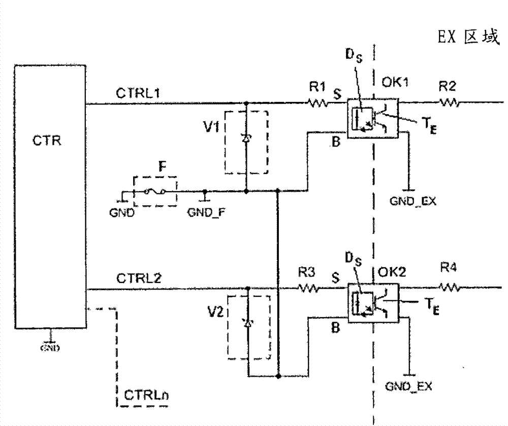
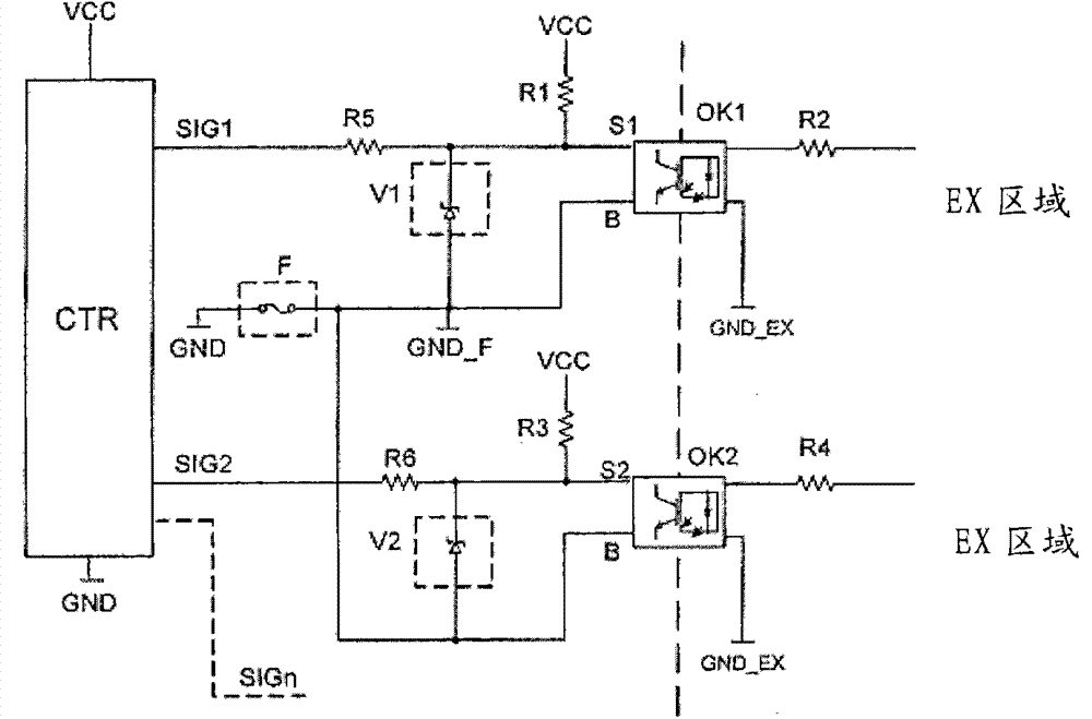
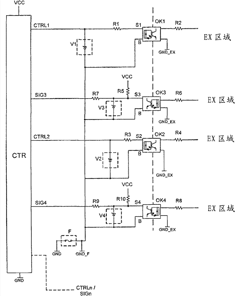
[0026] figure 1 A schematic diagram of a circuit arrangement is disclosed, with which at least two optocouplers OK1, OK2, ..., OK as galvanic isolation units n Provides overload protection. Optocoupler OK1, OK2, ..., OK n Provides galvanic separation of intrinsically safe areas (EX area) and non-intrinsically safe areas (left-hand area). In particular, an intrinsically safe area is an explosion protection area to which special requirements apply, such as specified in the standard DIN EN60079-11 (VDE0170-7).

[0027] In non-Ex areas, the galvanic isolating units OK1, OK2, ..., OK n Each of them has a control signal terminal S and a base terminal B. In the Ex zone EX area, the control signal terminal S_EX and the base terminal B_EX are provided in a corresponding manner. The signal terminal S_EX of the intrinsically safe area EX area is connected to a load (not shown) to be driven via a resistor R2. The base terminal B_EX is connected to the ground potential GND_EX of the ...


PUM


Abstract

A circuit arrangement having an overload protection for galvanic isolation units (OK1, OK2, . . . , OKn) for galvanic isolation from one another is described. The galvanic isolation units each have two regions galvanically isolated from one another and one of the regions has a control signal terminal (S) and a base terminal (B). The circuit arrangement have at least two such galvanic isolation units (OK1, OK2, . . . , OKn). From at least two of the galvanic isolation units (OK1, OK2, . . . , OKn) the base terminals (B) of a region are electrically conductively connected to one another and are connected to a base potential (GND) via a common fuse (F) connected in series.

Description

technical field [0001] The invention relates to a circuit arrangement with overload protection for a galvanic isolating unit for galvanically isolating circuit regions from one another, wherein each galvanically isolating unit has two mutually galvanically isolated regions and at least one of the regions has A control signal connection and a base signal connection, wherein the circuit arrangement has at least two such galvanic isolation units. Background technique [0002] Such circuit arrangements are especially necessary in input and / or output modules in intrinsically safe Ex areas. The circuit arrangement is used in combination with industrial controllers and building automation systems. When passing electrical signals in transition areas between intrinsically safe and non-intrinsically safe areas, specific rules need to be followed. These circuit areas must be galvanically isolated from each other, so that the energy transferred between these galvanically isolated circ...

Claims


Application Information

Patent Timeline
IPC IPC(8): H02H3/20
CPCH04L25/0266H02H3/023H04L25/26H03K17/7955H02H9/008H02H3/10H04B10/802H03K17/08146H02H9/041H02H9/02H02M3/33523
Inventor C·沃斯
Owner WAGO VERW GMBH
Learn More