Sample liquid injection jig set

A guiding device and liquid injection technology, applied in measuring tubes/pipettes, laboratory containers, instruments, etc., can solve the problems of reducing analysis efficiency, hindering reaction, dispersion, etc., and achieve safe operation and prevent touch Effect

Inactive Publication Date: 2014-06-04
SONY CORP
View PDF7 Cites 3 Cited by
  • Summary
  • Abstract
  • Description
  • Claims
  • Application Information

AI Technical Summary

Problems solved by technology

As a result, there is a problem that dispersion occurs in a large number of samples introduced into flow paths, reservoirs, etc., thereby reducing analysis accuracy and reducing analysis efficiency
In addition, when the heating of the sample is performed together with the accounting amplification reaction, it causes the bubbles remaining in the region to expand, thereby hindering the reaction and reducing the problem of analysis accuracy

Method used


Image

  • Sample liquid injection jig set
  • Sample liquid injection jig set
  • Sample liquid injection jig set

Examples


Embodiment Construction

[0045] Hereinafter, suitable modes for carrying out the present technology will be described with reference to the accompanying drawings. It is to be noted that the embodiments described below show examples of typical embodiments of the present technology, and therefore, the scope of the present technology is not narrowly interpreted by the embodiments. Description will be given according to the following order.

[0046] 1. Guide device according to the first embodiment

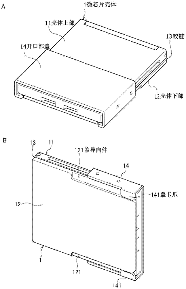
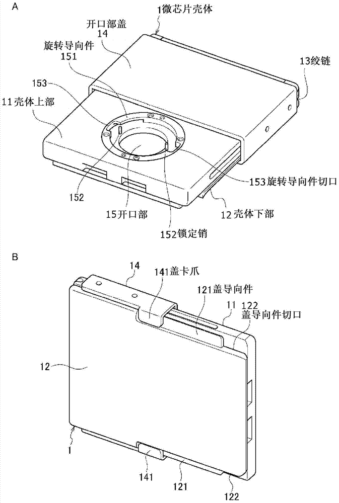
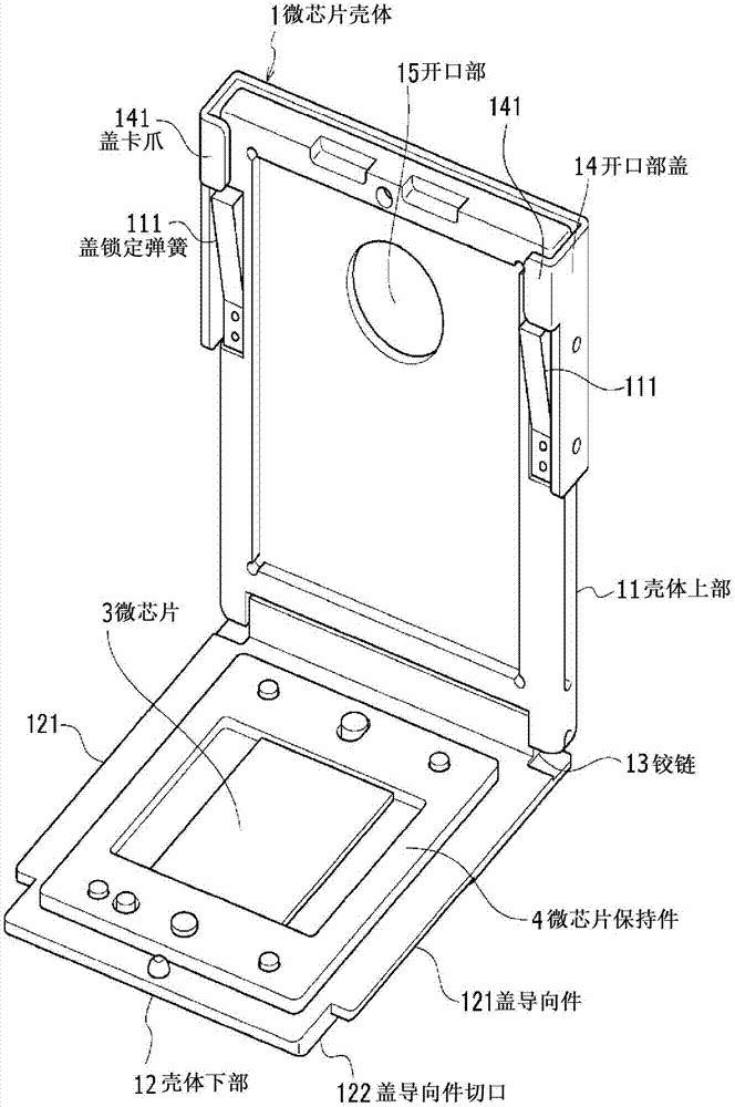
[0047] (1) Microchip housing

[0048] (2) microchip

[0049] (2-1) Structure of microchip

[0050] (2-2) Introducing the sample solution into the microchip

[0051] (3) Liquid injection guide

[0052] (4) Use the guiding device to inject the sample solution

[0053] 2. Guiding device according to the second embodiment

[0054] (1) Microchip housing

[0055] (2) Liquid injection guide

[0056] (3) Use the guiding device to inject the sample solution

[0057] 3. Guiding device according to the third e...


PUM


Abstract

A liquid injecting jig is provided. The liquid injecting jig includes a jig configuration including a plurality of parts adapted to be in cooperative engagement so as to position a channel within the jig configuration, wherein the jig configuration is adapted to fit an opening through which the channel is adapted to be received so as to expose the channel from the jig configuration. A jig set, a microchip case, and a microchip set are also provided.

Description

technical field [0001] The present technology relates to a sample liquid injection guide. More specifically, the present technology relates to a sample liquid injection guide device, which is constituted by including a microchip housing and a liquid injection guide, and which is used to inject a sample liquid into a microchip. Background technique [0002] In recent years, a microchip has been developed in which regions such as reservoirs and flow paths for performing chemical analysis or biological analysis are provided in a substrate by applying microfabrication technology from the semiconductor industry , the substrate is, for example, a substrate made of silicon or a substrate made of glass (for example, refer to Patent Document 1). Analytical systems using such microchips are called Micro TAS (Micro Total Analytical System), lab-on-a-chip, biochip, etc., and are used as a small size for realizing acceleration of analysis, high efficiency improvement or high integration...

Claims


Application Information

Patent Timeline
Patent Type & Authority Applications(China)
IPC IPC(8): B01L3/02
CPCB01L3/5027B01L3/022B01L2200/027G01N35/10B01L3/021
Inventor 渡边俊夫小岛健介濑川雄司渡边英俊加藤义明
Owner SONY CORP
Why Eureka
Try Eureka