
Transmission intermediate shaft circlip automatic feeding and pressing mechanism

A technology of automatic feeding and intermediate shaft, applied in assembly machines, metal processing, metal processing equipment, etc., can solve the problems of manual assembly of the circlip, and achieve the effect of solving the difficulty of manual assembly, high degree of assembly automation, and compact structure.

Inactive Publication Date: 2016-03-30
SHENYANG INST OF AUTOMATION - CHINESE ACAD OF SCI
View PDF5 Cites 2 Cited by
  • Summary
  • Abstract
  • Description
  • Claims
  • Application Information

AI Technical Summary

Problems solved by technology

This mechanism realizes the automatic loading, positioning and pressing of the circlip, and solves the problem of manual assembly of the original circlip.

Method used


Image

  • Transmission intermediate shaft circlip automatic feeding and pressing mechanism
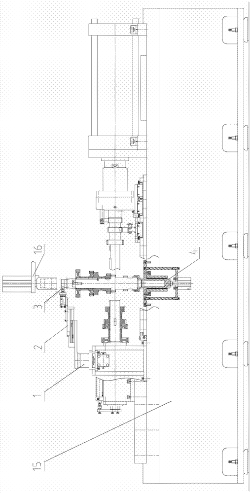
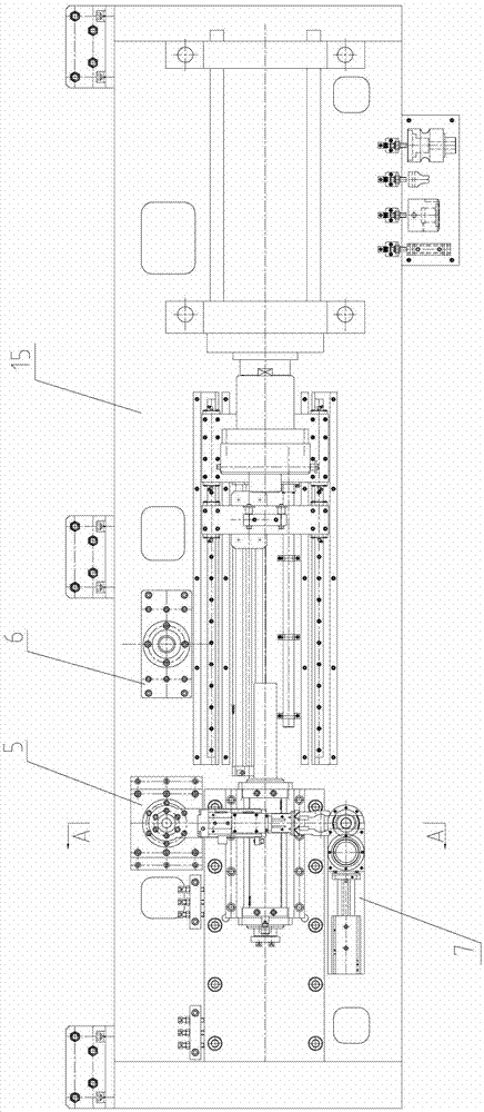
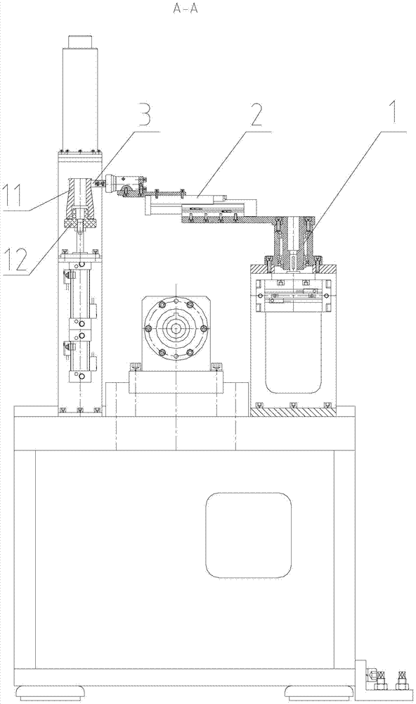
  • Transmission intermediate shaft circlip automatic feeding and pressing mechanism
  • Transmission intermediate shaft circlip automatic feeding and pressing mechanism

Examples


Embodiment Construction

[0021] The present invention will be further described below in conjunction with the accompanying drawings.

[0022] Such as Figure 1-4 As shown, the present invention includes a body 15, a press-fitting device 16 and a snap spring feeding and conveying mechanism, wherein the body 15 is the body of an intermediate shaft horizontal press. The feeding conveying mechanism of the snap spring includes a snap spring installation mechanism 7 installed on the body 15, a holding and rotating mechanism 5, a snap ring cover tooling 11, a snap ring cover tooling positioning mechanism 14 and an intermediate shaft lifting mechanism 4, wherein the snap ring The spring cover frock 11 is positioned on the snap spring cover frock positioning mechanism 14, the clip spring installation mechanism 7 is arranged on the top of the clip spring cover frock 11, and the intermediate shaft of the clip spring to be pressed is vertically positioned on the intermediate shaft lifting mechanism 4; The circli...


PUM


Abstract

The invention belongs to the technical field of transmission assembly and particularly relates to an automatic loading pressing mechanism for an intermediate shaft snap spring of a transmission. The mechanism comprises a body, a pressing unit and a snap spring loading delivery mechanism. The snap spring loading delivery mechanism comprises a snap spring mounting mechanism, a snapping rotation mechanism, a snap spring sleeve tooling, a snap spring sleeve tooling location mechanism and an intermediate shaft lifting mechanism. The snap spring sleeve tooling is located on the snap spring sleeve tooling location mechanism, the snap spring mounting mechanism is arranged above the snap spring sleeve tooling, the intermediate shaft on which the snap spring is to be pressed, is arranged on the intermediate shaft lifting mechanism vertically. The snap spring to be pressed is sleeved on the snap spring sleeve tooling through the snap spring mounting mechanism, the snapping rotation mechanism snaps and delivers the snap spring sleeve tooling with the snap spring sleeved to the upper portion of the intermediate shaft on which the snap spring is to be pressed, the intermediate shaft rises to be located with the snap spring sleeve tooling through the intermediate shaft lifting mechanism, and the pressing unit presses the snap spring sleeved on the snap spring sleeve tooling in a snap spring groove of the end of the intermediate shaft. By means of the mechanism, automatic loading, location and pressing of the snap spring are achieved, and the problem of the difficulty in prior manual assembly of snap springs is solved.

Description

technical field [0001] The invention belongs to the technical field of transmission assembly, in particular to an automatic feeding and pressing mechanism for a transmission intermediate shaft clamp spring. Background technique [0002] Due to the small size of the circlip set at the shaft end of the intermediate shaft of the transmission, there is no circlip pliers hole at the opening of the circlip, and the opening of the circlip needs to avoid the key on the intermediate shaft during the assembly process, so the traditional assembly of the circlip of the intermediate shaft is done manually. assembly. In order to improve assembly accuracy and assembly efficiency, and save manpower, it is very important to design a spring automatic feeding and pressing mechanism on the intermediate shaft horizontal press. Contents of the invention [0003] In view of the above problems, the object of the present invention is to provide an automatic feeding and pressing mechanism for the ...

Claims


Application Information

Patent Timeline
Patent Type & Authority Patents(China)
IPC IPC(8): B23P19/027B23P21/00
CPCB23P19/001B23P19/027
Inventor 于龙会常凯邢韵许胜利
Owner SHENYANG INST OF AUTOMATION - CHINESE ACAD OF SCI
Learn More