Blow moulding machine

A technology of a plastic container and a locking mechanism, which is applied in the special transmission machinery of the glass blowing machine, etc., can solve the problems of complex technology and poor durability.

Active Publication Date: 2014-06-11
KRONES AG
View PDF5 Cites 3 Cited by
  • Summary
  • Abstract
  • Description
  • Claims
  • Application Information

AI Technical Summary

Problems solved by technology

[0003] These steps have proven effective, however technically some are relatively complex or have disadvantages in terms of durability

Method used


Image

  • Blow moulding machine
  • Blow moulding machine
  • Blow moulding machine

Examples


Embodiment Construction

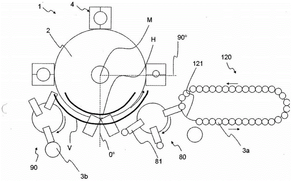
[0062] figure 1 A plant 1 for the production of plastic containers 3b according to the invention is shown. In the present example, the plastic pre-forms 3 a are first transported on a transport chain 121 and heated by a heating device 120 . The plastics material pre-forms 3 a heated in this way are then taken up by a feed star wheel 80 and transported to a plurality of forming stations 4 . In the present example, said feed star wheel 80 has a plurality of arms 81 which are rotatable relative to the star wheel and which in any case are provided with support elements ( not shown), such as clips, are used to support the plastic preform.

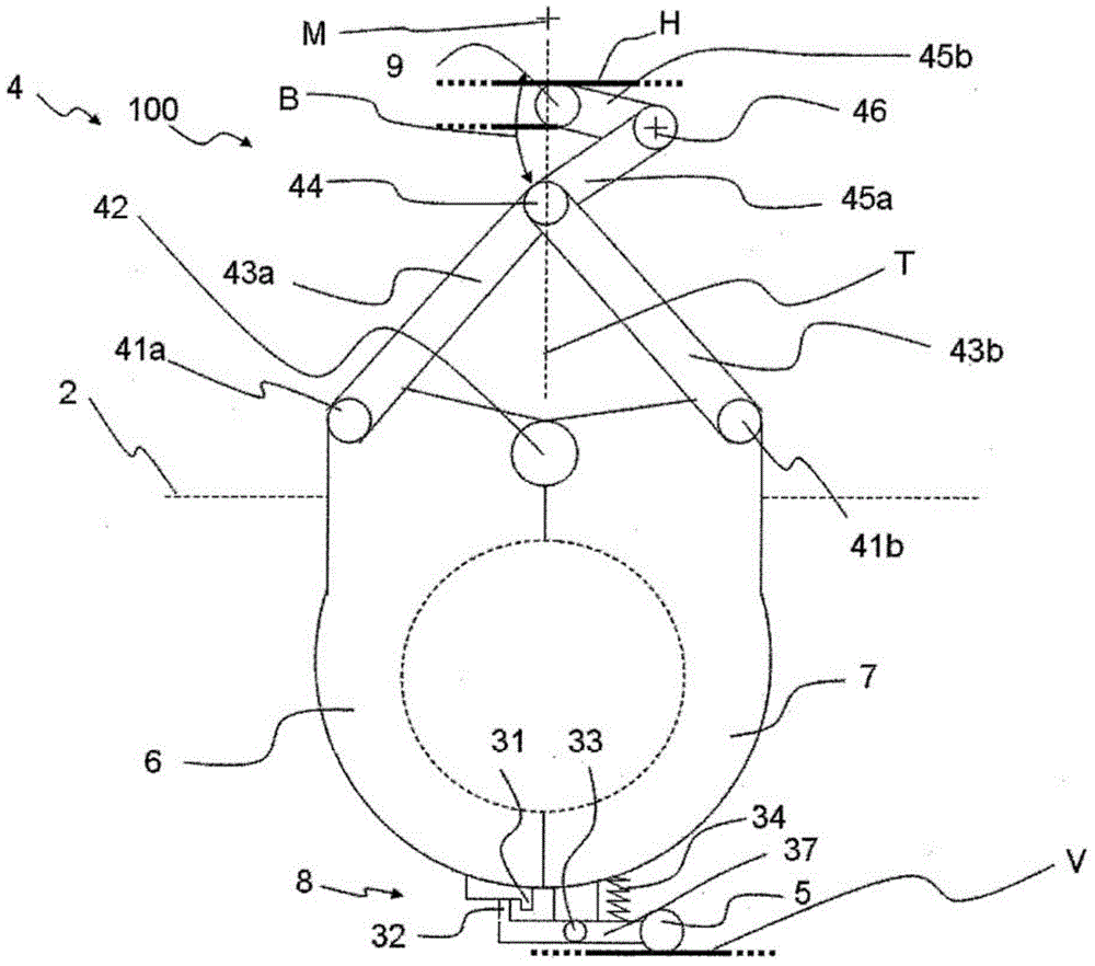
[0063] Reference numeral 2 relates to a rotatable carrier on which a plurality of forming stations 4 (only four are shown here in the figure) are arranged. In the present example, these forming stations 4 have a first blow mold carrier part 6 and a second blow mold carrier part 7 . The blow-molded parts are arranged on these carrier parts so...


PUM


Abstract

An apparatus is provided for the shaping of plastics material containers. The apparatus is provided with a movable carrier. A plurality of shaping stations for the shaping of plastics material pre-forms into plastics material containers are arranged on the movable carrier. The shaping stations are provided with blow mould carrier parts movable with respect to each other for opening and closing the shaping stations. The shaping stations are provided with a locking mechanism for holding the shaping stations in a closed state.

Description

technical field [0001] The invention relates to an apparatus for forming plastic or glass preforms into plastic containers. Background technique [0002] Such devices for forming plastic or glass preforms into plastic containers are known in the prior art. Usually, such devices have a rotatable carrier on which a plurality of blow molding stations are arranged. In this case, these blow molding or forming stations have molded parts. In any case the mold parts can be closed to form a cavity, so that the plastic or glass preform is expanded inside the cavity, in particular by the action of compressed air, to form the plastic container. In this case, a guide cam is usually provided, wherein the guide cam closes the two mold parts to one another. Furthermore, locking mechanisms (in part with separate guide cams) are known in the prior art, which lock the blow mold in the closed state. Very high pressures occur inside the blow mold, so this locking mechanism is useful. Thanks...

Claims


Application Information

Patent Timeline
Patent Type & Authority Applications(China)
IPC IPC(8): B29C49/28B29C49/42C03B9/40
CPCB29C49/56B29C2049/566B29C49/06B29C49/36B29C49/5602B29C49/5603B29C49/561B29C2049/5662B29C2949/0715
Inventor 托马斯·菲利普托马斯·斯皮策弗洛里安·格尔丁格尔托马斯·霍尔里格尔
Owner KRONES AG
Why Eureka
Try Eureka