Sole structure of crawler-type bionic wall-climbing robot and motion method thereof

A wall-climbing robot and crawler-type technology, applied in the field of bionic robots, can solve problems such as inability to adjust adaptively, fixed mechanical properties, etc., and achieve the effect of solving internal redundant forces

Inactive Publication Date: 2014-06-11
HEFEI INSTITUTES OF PHYSICAL SCIENCE - CHINESE ACAD OF SCI
View PDF5 Cites 11 Cited by
  • Summary
  • Abstract
  • Description
  • Claims
  • Application Information

AI Technical Summary

Problems solved by technology

The mechanical properties of this type of sole material are fixed, and it cannot be adaptively adjusted when...

Method used


Image

  • Sole structure of crawler-type bionic wall-climbing robot and motion method thereof
  • Sole structure of crawler-type bionic wall-climbing robot and motion method thereof
  • Sole structure of crawler-type bionic wall-climbing robot and motion method thereof

Examples


Embodiment 1

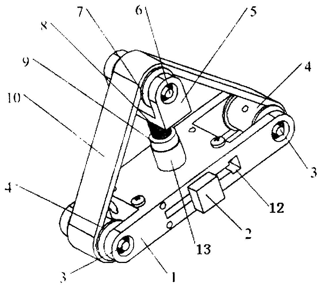
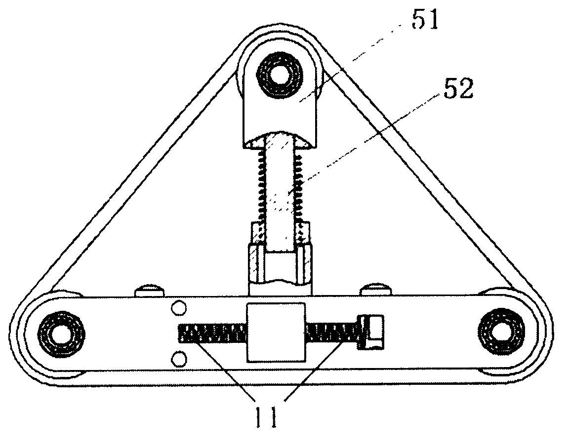
[0040] like Figure 1a and Figure 1bAs shown, a foot structure of a crawler-type bionic wall-climbing robot includes a fuselage frame 1, a rolling wheel 4, a tensioning mechanism, and an adhesive crawler 10. The rolling wheel 4 is installed on the fuselage frame through a rolling wheel shaft 3 1 at both ends, the tensioning mechanism includes a tensioning wheel frame 5, a tensioning spring 8, a miniature force sensor 9, a tensioning wheel 7, and a sleeve 13, the sleeve 1 is provided on the upper surface of the fuselage frame 1 , the upper surface of the sleeve 13 is provided with the miniature force sensor 9, the tensioning wheel frame 5 includes a shaft extension 52 and a mounting end 51, and the lower end of the shaft extension 52 passes through the miniature force sensor 9 and the sleeve 13. A tensioning spring 8 is sleeved on the shaft extension 52, and the tensioning spring 8 is arranged between the miniature force sensor 9 and the mounting end 51, and the tensioning whe...

Embodiment 2

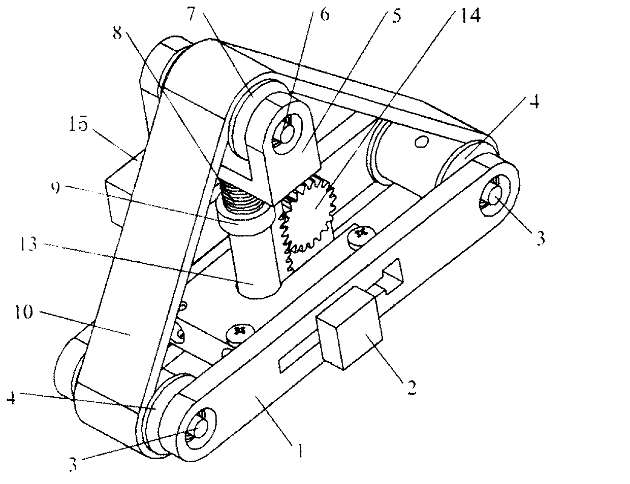
[0045] like Figure 2a , Figure 2b and Figure 2c As shown, the sleeve 13 is a lifting sleeve arranged on the upper surface of the fuselage frame 1, the outer side of the lifting sleeve is provided with a rack, and the fuselage frame 1 is provided with a tensioning The driving gear 14 of the motor 15 engages the rack of the lifting sleeve and drives the lifting sleeve to rise and fall.

[0046] like Figure 3a , Figure 3b , Figure 3c Shown is the movement method of the second embodiment of the foot sole structure of the anti-living wall-climbing robot traveling on a flat surface. like Figure 3a As shown, the robot body outputs motion commands of rotation and translation in the x-y plane to the sole of the foot by controlling the lateral movable member 2 . Through the rotating motion, the connecting line between the two rolling wheels of the sole of the foot and the wall surface forms a certain orientation angle α. With the sole of the foot in the suspended phase, t...


PUM


Abstract

The invention discloses a sole structure of a crawler-type bionic wall-climbing robot. The sole structure comprises a body frame, rolling wheels, a tension mechanism, an adhesion crawler belt and a driving mechanism, wherein the rolling wheels are arranged at the two ends of the body frame through rolling wheel axles; the tension mechanism comprises a tension wheel frame, a tension spring, a micro force sensor, a tension wheel and a sleeve; the sleeve is arranged on the upper surface of the body frame; the micro force sensor is arranged on the upper surface of the sleeve; the tension wheel frame comprises a shaft extension and a mounting end; the lower end of the shaft extension passes through the micro force sensor and the sleeve; the shaft extension is sleeved with the tension spring; the tension spring is arranged between the micro force sensor and the mounting end; the tension wheel is arranged at the mounting end through a tension wheel axle; the tension wheel is connected with the rolling wheels through the adhesion crawler belt; the driving mechanism is arranged on the body frame. Certain tangential displacement and posture angles are output by a robot body, so that adhesion, detachment and pressing of the sole are realized, and the robot is helped to walk and stop on a wall face.

Description

technical field [0001] The invention relates to the field of bionic robots, in particular to a foot sole structure of a crawler-type bionic wall-climbing robot and a movement method thereof. Background technique [0002] The three-dimensional space surface crawling robot has always been a research hotspot in the field of robotics. The use of wall-climbing robots can replace humans to perform tasks on steep walls, such as skyscraper exterior wall cleaning, oil and gas tank maintenance, and nuclear facility maintenance. The study found that there are millions of micron-scale bristles growing on the surface of the gecko's toes, and thousands of nano-scale villi at the top of each bristle. The van der Waals force (ie, intermolecular force) between these bristle arrays and the wall provides support for the giant gecko to stick and walk on the wall. The researchers use MEMS (Micro Electro Mechanical System) technology, NEMS (Nano Electro Mechanical System) technology, etc., and ...

Claims


Application Information

Patent Timeline
IPC IPC(8): B62D55/08B62D55/24B62D55/26B62D55/30
Inventor 吴晅张勇杰孙少明梅涛吴益靓
Owner HEFEI INSTITUTES OF PHYSICAL SCIENCE - CHINESE ACAD OF SCI
Why Eureka
Try Eureka