Hydraulic lifting travelling crane

A hydraulic and driving frame technology, which is applied in cranes, trolley cranes, transportation and packaging, etc., can solve the problems of combustion, danger, and easy to generate electric sparks, etc., and achieve large movable space, large lifting tonnage, and small installation space Effect

Inactive Publication Date: 2014-06-11
焦作市华科液压机械制造有限公司
View PDF6 Cites 4 Cited by
  • Summary
  • Abstract
  • Description
  • Claims
  • Application Information

AI Technical Summary

Problems solved by technology

Most of the lifting equipment currently used in our country is electric lifting equipment. Electric lifting equipment is easy to generate electric sparks during work, which may cause explosion and combustion of flammable gases. Therefore, electric lifting equipment is used in these flammable and explosive occasions. very dangerous, very inappropriate

Method used


Image

  • Hydraulic lifting travelling crane
  • Hydraulic lifting travelling crane
  • Hydraulic lifting travelling crane

Examples


Embodiment Construction

[0013] The present invention will be further described below in conjunction with the accompanying drawings and specific embodiments.

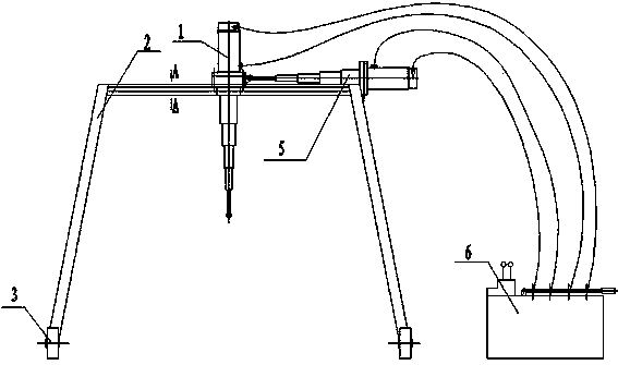
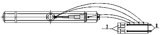
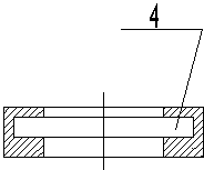
[0014] like figure 1 , 2 As shown in and 3, the hydraulic lifting crane of the present invention includes a lifting cylinder 1 and a traveling device, and the traveling device includes a traveling frame 2 and a traveling wheel 3 arranged at the bottom of the traveling frame 2, and the traveling frame 2 is provided with There is a sliding groove 4, the lifting cylinder 1 is provided with a mounting flange, the mounting flange is snapped into the sliding groove 4 and can move along the length direction of the sliding groove 4, and one side of the walking device is provided with a horizontal cylinder 5. The piston rod of the horizontal cylinder 5 is hinged to the lifting cylinder 1. The horizontal cylinder 5 and the lifting cylinder 1 are connected to the manual reversing hydraulic system 6 through pipelines. When the manual reversing hydraulic s...


PUM


Abstract

The invention discloses a hydraulic lifting travelling crane. The hydraulic lifting travelling crane comprises a lifting cylinder and a travelling device, wherein the travelling device comprises a travelling crane frame and travelling wheels, the travelling crane frame is provided with a slide groove, the lifting cylinder is provided with an installation flange which is clamped in the slide groove and can move along the length direction of the slide groove, a horizontal cylinder is arranged at one side of the travelling device, the piston rod of the horizontal cylinder is hinged with the lifting cylinder, the horizontal cylinder and the lifting cylinder are connected with a manual reversing hydraulic system through pipelines, and when the manual reversing hydraulic system works, the lifting cylinder acts, the piston rod of the lifting cylinder stretches and withdraws so as to lift up or lay down heavy objects; the horizontal cylinder acts, the piston rod of the horizontal cylinder stretches and withdraws so as to push or pull the lifting cylinder, so that the lifting cylinder slides in the slide groove through the installation flange so as to horizontally reciprocate on the travelling crane frame. The lifting travelling crane can effectively prevent generation of electric spark, and is widely used in a coal mine, a gasoline station, a gas station and the like where combustible gas exists.

Description

technical field [0001] The invention relates to the technical field of hydraulic equipment manufacturing, in particular to a hydraulic lifting crane. Background technique [0002] In places where there are flammable gases such as coal mines, petroleum, gas stations and gas stations in our country, where the ball is flammable and explosive, the safety requirements of these occasions are very high, and these occasions still need to be used at certain times Lifting equipment is used to get some work done. Most of the lifting equipment currently used in our country is electric lifting equipment. Electric lifting equipment is easy to generate electric sparks during work, which may cause explosion and combustion of flammable gases. Therefore, electric lifting equipment is used in these flammable and explosive occasions. Very dangerous and very inappropriate. Contents of the invention [0003] The purpose of the present invention is to address the defects of the above-mentioned...

Claims


Application Information

Patent Timeline
Patent Type & Authority Applications(China)
IPC IPC(8): B66C19/00
Inventor 何鹏李凤芹乔新艳
Owner 焦作市华科液压机械制造有限公司
Why Eureka
Try Eureka