[0022] Hereinafter, the converter slagging device of the present invention and the method for controlling converter slagging by using the device will be described in detail with reference to the accompanying drawings and exemplary embodiments.
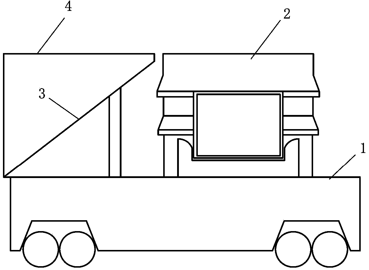
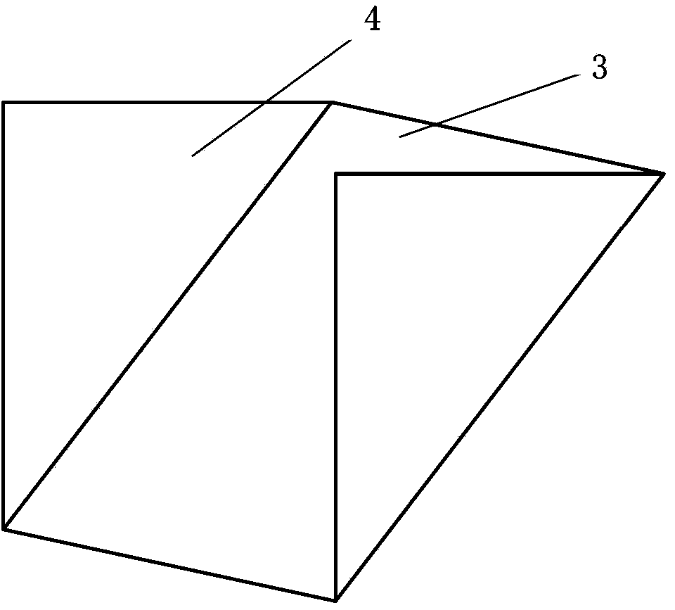
[0023] figure 1 Is a schematic diagram of a converter slag removing device according to an exemplary embodiment of the present invention, figure 2 It is a perspective view of a converter slagging device according to an exemplary embodiment of the present invention. Refer to below figure 1 with figure 2 To describe in detail the converter slagging device of the present invention and the method of using the device to control converter slagging.
[0024] Reference figure 1 with figure 2 , The converter slag lowering device according to an exemplary embodiment of the present invention includes a lower slag runner 3 and a retaining wall 4. The lower slag flow channel 3 is a plate-shaped structure having a first surface and a second surface, the first surface faces away from the ladle car 1 and the second surface faces the ladle car 1. The lower slag runner 3 is fixed on the ladle car 1 with a certain inclination angle, and is arranged in front of the ladle 2 in the direction of tapping the converter. The lower slag runner 3 includes a first end and a second end along its height direction. The first end is close to the ladle 2 and the second end is far away from the ladle 2, and the height of the first end is higher than the height of the second end. The lower slag runner 3 can introduce the steel slag poured from the converter into the steel slag tank located below the second end of the lower slag runner 3. The retaining wall 4 is divided into a first retaining wall and a second retaining wall, and they are respectively fixed on the left and right sides of the first surface of the lower slag runner 3, so that the retaining wall 4 and the lower slag runner 3 together define a channel through which steel slag flows. At the end of tapping, the position of the converter is adjusted to be close to the first end of the lower slag runner 3, and the furnace is lifted in time when the molten steel is exhausted, so that the steel slag in the converter is poured onto and along the lower slag runner 3 The first surface of the lower slag runner 3 flows into the steel slag tank from the second end of the lower slag runner 3. At this time, the retaining walls 4 located on the left and right sides of the lower slag runner 3 can block the splashes generated during the dumping of the steel slag on the lower slag runner 3 of the converter, so as to avoid the high temperature steel slag splashing on the left and right car body equipment of the ladle car 1. Burned. Although the lower slag runner 3 has a plate-like structure, the present invention is not limited to this, that is, the lower slag runner 3 may have a certain arc, and the arc may be determined according to specific conditions.
[0025] According to an exemplary embodiment of the present invention, the lower slag runner 3 may be welded and made of metal plates (for example, steel plates), or may be made of refractory materials. When the lower slag runner 3 is made of a metal plate, refractory bricks can be laid on the metal plate of the lower slag runner 3 to reduce the corrosion of steel slag to the metal plate, and it is also conducive to the adhesion of steel slag on the first surface of the lower slag runner The removal. There is no special requirement for the thickness of the lower slag runner 3, and may be the smallest thickness that can withstand the high-speed impact of the slag flow. The width of the lower slag runner 3 can be determined according to the amount of slag discharged from the converter, the slag dumping speed and the viscosity of the slag.
[0026] According to an exemplary embodiment of the present invention, the length of the lower slag runner 3 can be determined according to the position of the first end and the second end of the lower slag runner 3 and the angle between the lower slag runner 3 and the horizontal plane, so that the lower slag runner The first end of the channel 3 is close to the ladle 2 or in contact with the ladle 2, the second end is located on the upper part of the slag tank, and the first end is higher than the second end. Preferably, the length of the lower slag runner 3 can be increased to reduce the level of the second end, which can reduce the range of splashing caused when the steel slag flows into the steel slag tank from the second end. However, the present invention is not limited to this. In other words, slag storage equipment can be set up so that steel slag flows into the slag storage equipment through the second end of the lower slag flow channel 3. At this time, the height of the slag storage equipment can be controlled to reduce The splash range caused by the steel slag flowing into the slag storage equipment can reduce the length of the lower slag runner 3.
[0027] According to the exemplary embodiment of the present invention, preferably, the angle between the lower slag runner 3 and the horizontal plane is 45°, which can facilitate the drainage of the steel slag by the lower slag runner 3, and can reduce the dumping of steel slag from the converter. The height of the back splash in the lower slag runner 3 is also beneficial to the treatment of the cooled slag remaining on the lower slag runner 3.
[0028] According to an exemplary embodiment of the present invention, the retaining wall 4 may be welded to the left and right sides of the first surface of the lower slag runner 3 by a metal plate (for example, steel plate) perpendicular to the first surface of the lower slag runner 3 to Preventing the splashing and burning of the left and right car body equipment of the ladle car 1 during the process of pouring steel slag into the lower slag runner 3. The height of the retaining wall 4 may be the minimum height to prevent splashing during the process of pouring steel slag into the lower slag runner 3. However, the present invention is not limited to this, that is to say, the retaining wall 4 can be formed by masonry of refractory bricks, and the angle between the first retaining wall and/or the second retaining wall and the first surface of the lower slag runner 3 It can be obtuse or acute.
[0029] According to an exemplary embodiment of the present invention, the length of the first retaining wall and the second retaining wall may be equal and not greater than the length of the lower slag runner 3. However, the present invention is not limited to this, that is to say, the length of the first retaining wall and the second retaining wall can be the vehicle body equipment that can prevent the steel slag falling into the lower slag runner 3 from splashing and prevent the steel slag from flowing to the ladle car 1 Of any length.
[0030] According to an exemplary embodiment of the present invention, the first end of the lower slag runner 3 may not be higher than the ladle mouth of the ladle 2, but the present invention is not limited to this.
[0031] Hereinafter, the method for controlling the slagging of a converter using the above-mentioned device will be described in detail with reference to the accompanying drawings and in conjunction with exemplary embodiments of the present invention.
[0032] First, at the end of the converter tapping, the ladle car 1 is operated to bring the converter tapping steel stream close to the device. Specifically, at the end of tapping, operate the ladle car 1 to jog to bring the steel flow close to the first end of the lower slag runner 3 and ensure that the steel flow flows into the ladle 2. In this state, the steel flow is increased to a lesser extent. The tilt angle of the large converter can pour molten steel and/or steel slag into the lower slag runner 3.
[0033] Secondly, when the molten steel of the converter is exhausted, a furnace raising operation is performed to increase the tilting angle of the converter, so that the converter slag flow can flow into the lower slag runner 3. Specifically, the furnace raising operation is performed when the molten steel is exhausted. At this time, the ladle car 1 does not follow the flow (that is, does not follow the slag flow and moves). As the tilting angle of the converter increases, the slag flow in the converter directly flows out of the tapping hole into the lower slag runner 3 and flows along the first surface of the lower slag runner 3 from the second end of the lower slag runner 3. In the slag storage tank below the second end. At this time, since the ladle car does not follow the flow, the steel slag is prevented from being poured into the ladle, and the quality of molten steel is improved.
[0034] According to the exemplary embodiment of the present invention, when the converter is tapped, preferably, a slag monitoring device can be installed near the converter and/or a tapping slag blocking device can be installed in the converter, so that the converter slag can be controlled more accurately Operation to reduce the excessive molten steel entrained in the steel slag during the slagging process of the converter and to prevent the steel slag from flowing into the ladle 2.
[0035] According to the converter slagging device and the method for controlling converter slagging using the device of the present invention, when the molten steel is exhausted, the steel slag can be poured into the lower slag flow channel 3 and introduced into the slag storage tank through the furnace lifting operation in only 1 second In this way, the pollution of molten steel caused by steel slag flowing into the ladle 2 is avoided. In addition, the retaining walls 4 arranged on the left and right sides of the lower slag runner 3 also avoid splashing and burning equipment on the left and right sides of the ladle car caused by steel slag poured into the lower slag runner 3 during the slagging process of the converter.