AI technical title is built by PatSnap AI team. It summarizes the technical point description of the patent document.
An electromagnetic speed regulation and magnetic pole technology, applied in asynchronous induction motors, electrical components, electromechanical devices, etc., can solve the problems of complex mechanical device structure, small size of permanent magnets, limited speed regulation range, etc., to improve reliability and low cost. , the effect of reducing the current impact
Inactive Publication Date: 2016-08-31
杨玉岗
View PDF5 Cites 0 Cited by
Summary
Abstract
Description
Claims
Application Information
AI Technical Summary
This helps you quickly interpret patents by identifying the three key elements:
Problems solved by technology
Method used
Benefits of technology
Problems solved by technology
Its main disadvantages are as follows: First, the permanent magnet is small in size, the torque generated is small, and the speed regulation range is limited; second, the permanent magnet will be demagnetized or even demagnetized when it is heated and operated for a long time; third, the mechanical device structure for adjusting the air gap complex
Method used
Image
Click on the blue label to locate the original text in one second.
Reading with bidirectional positioning of images and text.
Examples
Embodiment 1
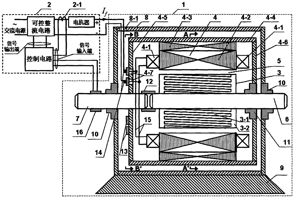
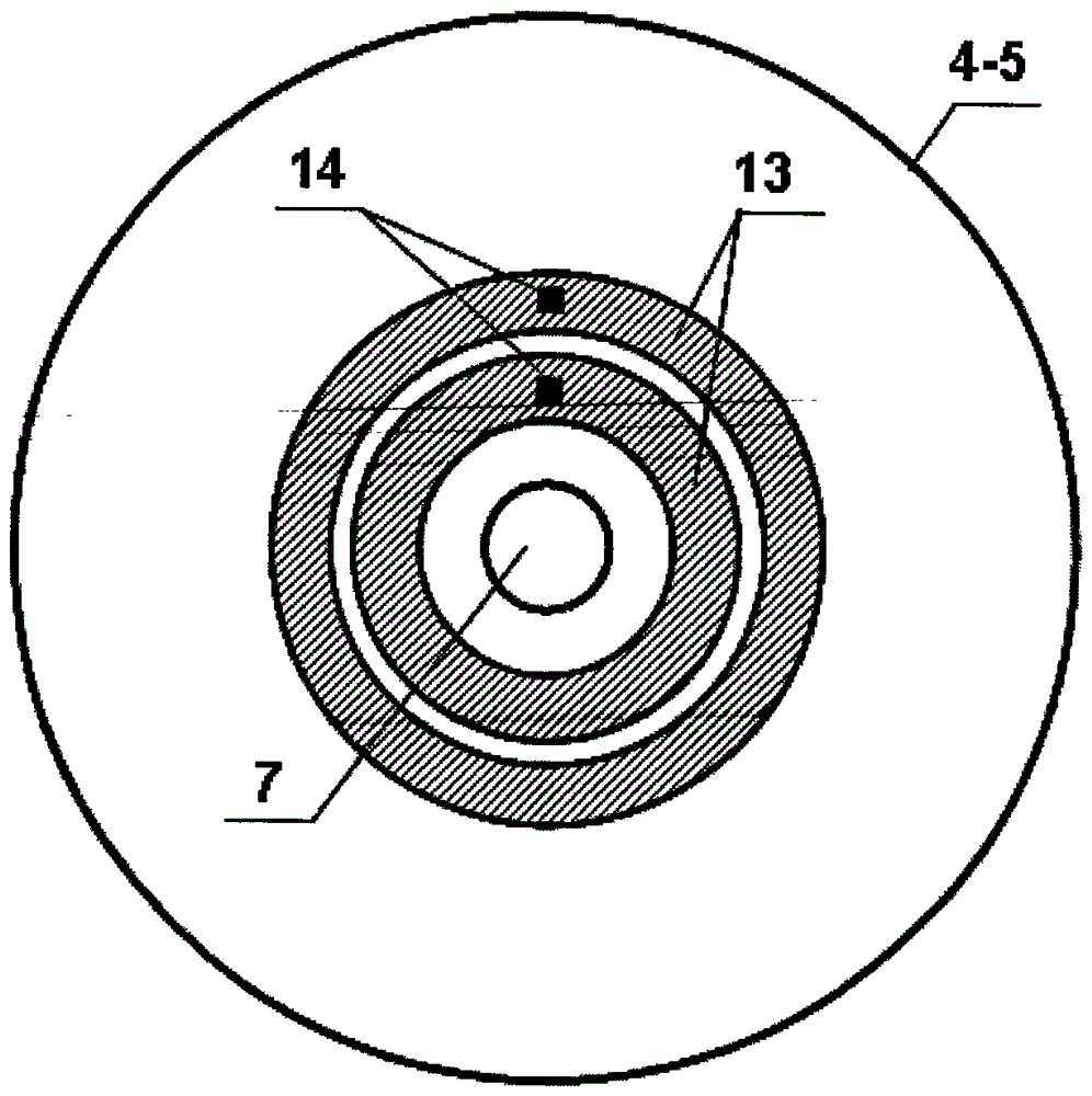
[0033] Refer to attached figure 1 , 2 , an electromagnetic speed regulating machine, composed of an electromagnetic speed regulating machine body 1 and a DC excitation circuit 2. Electromagnetic governor body 1 consists of inner rotor 3, outer rotor 4, inner rotor shaft 6, outer rotor shaft 7, casing 8, frame 9, bearing 10, outer rotor bearing 11, combined bearing 12, conductive slip ring 13, Brush 14, wire 15, speed sensor 16 constitute; DC excitation circuit 2 is constituted by controllable rectification circuit, current sensor 2-1, reactor, control circuit and connecting wire.
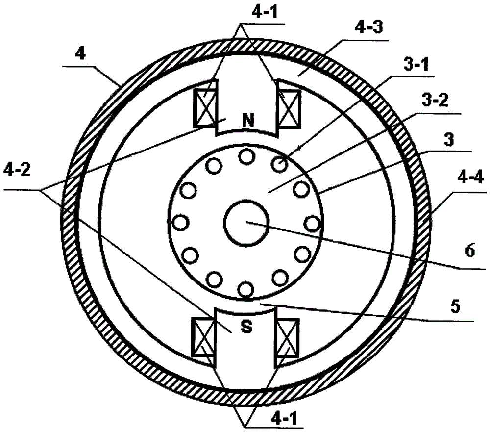
[0034]The inner rotor 3 includes a squirrel-cage winding 3-1 and an iron core 3-2, which is the same as the rotor of a traditional squirrel-cage AC asynchronous motor; the inner rotor 3 is sleeved on the inner rotor shaft 6; the inner rotor shaft 6 It is installed on the casing 8 and the outer rotor end cover 4-6 through two bearings 10, 11; the casing 8 is fixed on the frame 9.
[0035] The oute...
Embodiment 2
[0040] Refer to attached Image 6 , another embodiment of an electromagnetic speed regulating machine. The two iron core poles 4-2 of the outer rotor 4 in the first embodiment are increased to four, and by connecting the concentrated winding 4-1 on the iron core poles with the positive and negative output terminals of the DC excitation circuit 2, two adjacent The polarities of the core poles 4-2 are reversed. By analogy, the number of core poles can be increased to six, eight, ten, twelve, etc.
Embodiment 3
[0042] Refer to attached Figure 7 , another embodiment of an electromagnetic speed regulating machine. In Embodiment 1, the outer rotor cover 4-6 and the connected bearing 10 are removed, so that the outer rotor 4 becomes a cup-shaped structure.
PUM
Abstract
An electromagnetic speed regulator comprises an electromagnetic speed regulator body and a direct current excitation circuit. The electromagnetic speed regulator body is composed of an inner rotor, an outer rotor, an inner rotor shaft, an outer rotor shaft, a bearing, a combined bearing, conductive sliding rings, electric brushes, a conductive wire, a rotating speed sensor, a machine shell and a machine base; the direct current excitation circuit is composed of a controllable rectification circuit, a current sensor, an electric reactor, a control circuit and a connection conductive wire. A fixed air gap is formed between the inner rotor and an iron core magnetic pole of the outer rotor. The two conductive sliding rings are arranged on an outer rotor supporting plate, and the two electric brushes make sliding contact with the surfaces of the two conductive sliding rings; the conductive sliding rings are connected with a concentrated winding of the outer rotor, and the positive output end and the negative output end of the direct excitation circuit are connected with the two electric brushes. The inner rotor shaft and the outer rotor shaft are connected through the combined bearing. The electromagnetic speed regulator has the advantages of replacing a frequency converter, and providing a motor speed regulation method achieving high efficiency, energy conservation, firmness, reliability, low cost, no-load starting and no electromagnetic interference.
Description
technical field [0001] The invention relates to an electromechanical integrated electromagnetic speed-regulating drive system, in particular to an electromagnetic speed-regulating machine, which can be widely used in various fields requiring speed-regulating drives. Background technique [0002] According to statistics, my country's per unit energy consumption is five times that of developed countries, and it has remained high for a long time, and the serious waste of electric energy is one of the main reasons. Taking large-scale fans and water pumps as an example, the driving motor voltage is 3-10kV AC, and the power reaches more than 3000kW. In the past, a lot of electric energy was wasted due to the long-term use of constant-speed drive. When the fan and water pump output low flow, the motor runs at low speed, so that the power supply can achieve low power output, thereby saving electric energy. However, there are many restrictions on the use of variable frequency speed ...
Claims
Application Information
Patent Timeline
Application Date:The date an application was filed.
Publication Date:The date a patent or application was officially published.
First Publication Date:The earliest publication date of a patent with the same application number.
Issue Date:Publication date of the patent grant document.
PCT Entry Date:The Entry date of PCT National Phase.
Estimated Expiry Date:The statutory expiry date of a patent right according to the Patent Law, and it is the longest term of protection that the patent right can achieve without the termination of the patent right due to other reasons(Term extension factor has been taken into account ).
Invalid Date:Actual expiry date is based on effective date or publication date of legal transaction data of invalid patent.

