Supercharge Your Innovation With Domain-Expert AI Agents!

Rotary electric machine

A technology for rotating machines and rotating shafts, applied in electronic commutators, electromechanical devices, electrical components, etc., to solve problems such as reducing the detection accuracy of position sensors

Inactive Publication Date: 2014-06-11
DENSO CORP
View PDF7 Cites 8 Cited by
  • Summary
  • Abstract
  • Description
  • Claims
  • Application Information

AI Technical Summary

Problems solved by technology

This leaked magnetic flux is likely to degrade the detection accuracy of the position sensor

Method used


Image

  • Rotary electric machine
  • Rotary electric machine
  • Rotary electric machine

Examples


no. 1 approach )

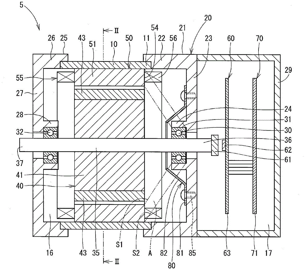
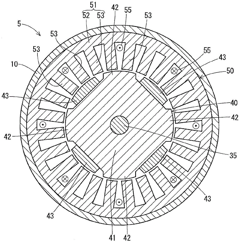
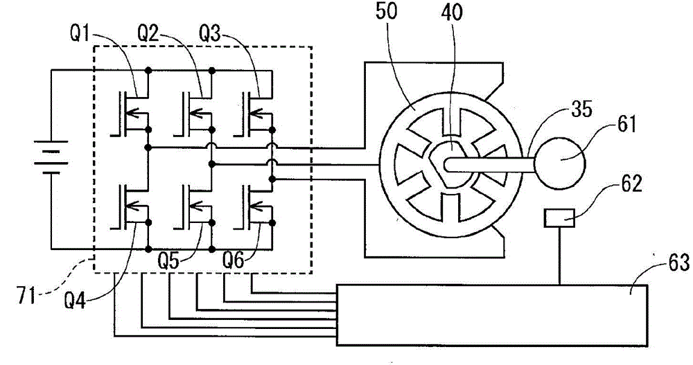
[0029] refer to Figure 1 to Figure 5 , the motor 5 is configured as a driving power source for a vehicle electric power steering system (not shown). The motor 5 is a three-phase brushless motor, and is composed of a casing 10, a housing 20, a first bearing 30, a second bearing 32, a rotating shaft 35, a rotor 40, a stator 50, a magnetic angle sensor 60 and an electronic drive control device 70. form.

[0030] The housing 10 is a cylindrical member made of soft magnetic material. The housing 20 is formed by a cup-shaped first housing part 21 and a cup-shaped second housing part 25 , the first housing part 21 being formed by a first cylindrical part 22 and a first bottom 23 . The first cylindrical portion 22 is secured to one axial end of the housing 10 by a sleeve-joint fit. The first bottom 23 closes one axial end of the first cylindrical portion 22 at the side opposite to the housing 10 . The first bottom portion 23 has a first bearing holding portion 24 extending toward...

no. 2 approach )

[0045] Such as Figure 6 As shown, in the motor 100 according to the second embodiment, the first bottom portion 23 of the housing 20 has the engaging protrusion 101 protruding toward the stator 50 . The engagement protrusion 101 has a top end portion that is crimped radially inward, thereby additionally fixing the first flange portion 81 of the magnetic member 80 by the bolt 85 .

[0046] According to the second embodiment, in addition to the same advantages provided by the first embodiment, the soft magnetic member 80 can be firmly fixed to the bottom 23 of the housing 20 .

no. 3 approach )

[0048] Such as Figure 7 As shown, in the motor 110 according to the third embodiment, a vibration damping member 111 is interposed between the soft magnetic member 80 and the first bottom portion 23 of the housing 20 . The first flange portion 81 of the soft magnetic member 80 is fixed to the first bottom portion 23 by rivets 112 .

[0049] According to the third embodiment, in addition to the same advantages provided by the first embodiment, the metal contact between the soft magnetic member 80 and the housing 20 is reduced, and thus it is possible to reduce noise generated by slight vibration between metals .


PUM


Abstract

The invention discloses an rotary electric machine. A housing (20) and a rotary shaft (35) of the motor (5) are formed of non-magnetic material. A soft magnetic member (80) is provided between a first axial end surface of a fixed core (51) and a bearing (30). The soft magnetic member (80) is provided on the fixed core (51) side relative to the first bearing (30) thereby to suppress magnetic flux leaking to a vicinity of one end part of the rotary shaft (35) by leading the magnetic flux, which is generated from a rotor (40), to the rotor core (41) through the fixed core (51) and a casing (10). A magnetic angular position sensor (60) fixed to one end part (36) of the rotary shaft (35) can detect a magnetic angular position of the rotor (40) accurately without being affected by external magnetic field. As a result, noise generated by vibration of the motor (5) can be suppressed.

Description

technical field [0001] The present invention relates to an electric rotary machine. Background technique [0002] In recent years, electric rotating machines such as motors using permanent magnets have achieved higher output power through rare earth permanent magnets. Among rare earth magnets, neodymium-iron-boron magnets especially have high performance. Rare earth magnets are not readily available as their production locations are limited to specific regions. It is therefore desired to reduce the amount of such magnets used. JP-A-2010-0288349 discloses a rotor of a common pole type electric rotating machine in which permanent magnets are arranged only at one side of a magnetic pole. [0003] However, in a common pole type motor, the entire yoke of the rotor is magnetized to the magnetic pole polarity of the portion that the permanent magnets contact. The magnetic flux flow thus turns around the outer peripheral portion of the stator and returns to the yoke central port...

Claims


Application Information

Patent Timeline
Patent Type & Authority Applications(China)
IPC IPC(8): H02K29/06H02K29/03H02K1/24H02K1/16
CPCH02K11/0005H02K11/0021H02K3/12H02K5/1732H02K11/215H02P6/16
Inventor 谷口真林二郎稻垣辰也内藤昭仁富泽弘贵山田正明山崎雅志松尾康史宫地修平瓜生信彦
Owner DENSO CORP
Features
  • R&D
  • Intellectual Property
  • Life Sciences
  • Materials
  • Tech Scout
  • Unparalleled Data Quality
  • Higher Quality Content
  • 60% Fewer Hallucinations
Learn More