
Wire guide rings for spinning or winding machines

A wire guide and winding machine technology, applied in textiles and papermaking, etc., can solve problems such as wire winding, and achieve the effect of prolonging the service life and avoiding wiping off.

Inactive Publication Date: 2016-09-21
DITF DEUT INST FUR TEXTIL UND FASERFORSCHUNG DENKENDORF
View PDF7 Cites 0 Cited by
  • Summary
  • Abstract
  • Description
  • Claims
  • Application Information

AI Technical Summary

Problems solved by technology

This difference in rotational speed will then cause the coiling of the wire

Method used


Image

  • Wire guide rings for spinning or winding machines
  • Wire guide rings for spinning or winding machines
  • Wire guide rings for spinning or winding machines

Examples


Embodiment Construction

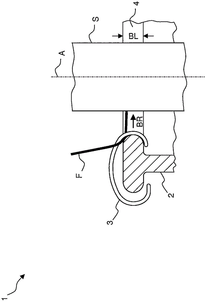
[0039] figure 1 An embodiment of a winding device 1 of a ring spinning machine with a thread guide ring 2 according to the invention is shown schematically. The winding device 1 is used for winding the thread F to be moved onto a reel S. Concentrically and rotationally fixed on a spindle, not shown, is a reel S, which is actively driven in rotation about a vertical axis A. For this purpose, the wire guide ring 2 is likewise arranged concentrically. The annular movement 3 is attached to the wire guide ring 2 in such a way that it can move circumferentially around the reel S in the set movement direction BR. Furthermore, the wire guide ring 2 has a running surface 4 along which the annular movement part 3 can slide. The working surface 4 is assigned to the reel S and has a width BL.

[0040] The wire F, fed axially from the top, is hooked on the annular movement 3 so that the wire F is reversed and fed to the spool S substantially tangentially during winding. The annular mo...


PUM


Abstract

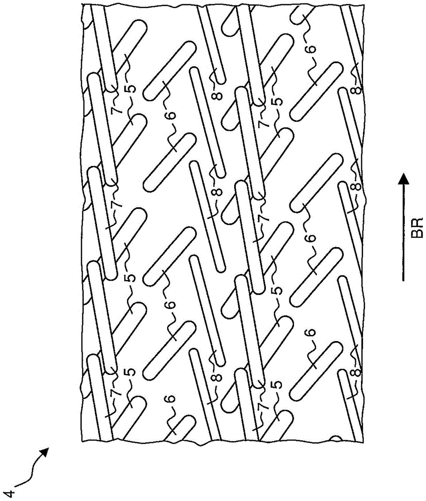
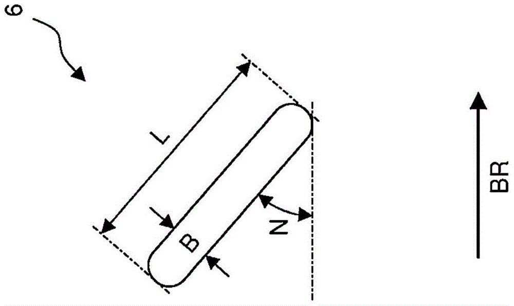
The invention relates to a thread guiding ring for a ring spinning machine or a twisting machine, comprising a running surface (4) for a ring traveler (3), which deflects the thread (F) during the winding of a thread (F) onto a bobbin tube (S) and in the process is moved by the thread (F) along the running surface (4), wherein the running surface (4) has grooves (5, 6, 7, 8), which are arranged at an angle to an intended direction of motion (BR) of the ring traveler (3).

Description

technical field [0001] The present invention relates to a thread guide ring for a ring spinning machine or a winding machine having a working surface for an annular movement which reverses the thread when it is being wound on a drum and wherein the The line moves along the work surface. Background technique [0002] The usual task of a ring spinning machine is to impart strength by rotating the fiber tape supplied to the spinning machine and to wind the rotating fiber tape for storage, transport or further processing purposes. Therein, the fiber tapes fed to the ring spinning machine are usually so-called rovings, which usually have only a weak rotation protection. A so-called yarn is then produced from these rovings by further rotation. [0003] In contrast to this, the task of the winding machine is to spin together a large number of yarns that are fed at the same time, thereby producing a so-called spinning thread. The yarn should likewise be wound in a suitable manner...

Claims


Application Information

Patent Timeline
Patent Type & Authority Patents(China)
IPC IPC(8): D01H7/56D01H7/58D01H7/62
CPCD01H7/62D01H7/602
Inventor 于尔根·施奈德乌韦·海特曼拉里莎·奥什克斯
Owner DITF DEUT INST FUR TEXTIL UND FASERFORSCHUNG DENKENDORF
Learn More