Coating dryer and its special air nozzle with buffer structure

A buffer structure, drying machine technology, applied in the direction of the surface coating liquid device, coating, pretreatment surface, etc., can solve the problems of inconsistency, unstable wind speed foil, jitter coating thickness, etc., to ensure stability The effect of avoiding inconsistent coating thickness and stabilizing thrust

Active Publication Date: 2016-02-17
SHENZHEN HAONENG TECH
View PDF5 Cites 0 Cited by
  • Summary
  • Abstract
  • Description
  • Claims
  • Application Information

AI Technical Summary

Problems solved by technology

Further, by image 3 It can be seen that the air nozzle 60 of the existing coating dryer is designed to disperse the structure of two air outlets 61 left and right, which makes it easy for the wind 100 in the air chamber to flow to the air outlet of the air nozzle 60 inside due to fluid The vortex 62 is formed by the sudden change of the passing ventilation cross-sectional area. It is measured by experiments that the generation of the vortex 62 will cause the wind speed deviation of the wind nozzle 60 to reach 2-3 m / min when the average speed of the air outlet wind speed is 8 m / min, and the wind speed is not high. Stabilization can cause the foil to vibrate resulting in inconsistent coating thickness

Method used


Image

  • Coating dryer and its special air nozzle with buffer structure
  • Coating dryer and its special air nozzle with buffer structure
  • Coating dryer and its special air nozzle with buffer structure

Examples


Embodiment 1

[0025] In the above structure, the section of the air chamber 40 of the air nozzle is an isosceles triangle, and the straight-through section is connected to the apex of the isosceles triangle. As a general choice, the shape of the air chamber 40 will not affect the wind speed of the wind blown out of the final air outlet. However, if the air chamber is designed as an isosceles triangle, not only can the fluid flow into the air chamber 40 of the air nozzle have better fluidity, but also the structure of the air chamber 40 can be easily produced.

Embodiment 2

[0027] In the above structure, the length of the straight section is not less than 20mm. It can be seen from the above that the straight-through section 51 plays a key role in the tuyere, and in order to ensure its pressure equalization effect, the length of the straight-through section should not be less than 20 mm. Theoretically, it is the same as the principle of increasing the barrel length and the stability of the outgoing shells, so the longer the straight-through section can have a better balance on the passing wind, but considering the actual product application environment, after repeated experiments , optimally, the length of the through section is 20-28mm is optimal.

Embodiment 3

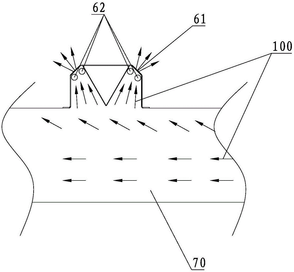
[0029] Further, an additional support plate 6 may be provided outside the air outlet of the bent section 52 , and a protective edge 61 is formed at the end of the support plate 6 bent inward toward the air chamber 50 of the air nozzle. The length of the supporting plate 6 is as long as the conditions permit. By adding the supporting plate 6, the wind energy blown out by the air outlet after equalization can overflow along the supporting plate 6 to form an air cushion surface. The stability makes the wind blown out of the tuyere form a stable upward thrust on the foil, which can better ensure that the foil will not vibrate in the oven. Avoid the problem of inconsistent coating thickness to the greatest extent. The protective edge 61 can enhance the strength of the supporting plate 6 and avoid damage to the foil after deformation.


PUM


Abstract

The invention provides a coating dryer and an air nozzle with a buffer structure special for the coating dryer. The air nozzle comprises an air chamber, a straight section and a bending section, one end of the straight section is communicated with the air chamber, the other end of the straight section is connected with one end of the bending section, the other end of the bending section is provided with an air outlet, and the bending section and the straight section are arranged in an obtuse angle mode. The straight section is arranged in front of an air outlet of the air nozzle, so that flow is led to pass through a section of flat channel. Due to the fact that sudden size variation of the ventilation area does not happen, eddies can not be caused, a pressure equalizing area can be formed in the straight section instead, and the stability of the air speed is guaranteed. The bending section is additionally arranged in front of the air outlet, so that the air does not directly blow a foil band, and the air slowly blows the foil band with an angle. Accordingly, when the air nozzle is applied to the coating dryer, the air speed after pressure equalizing is stable so that upward pushing force formed by the air blown out from the air nozzle to foil materials can be stable, the chattering phenomenon of the foil materials can not happen in a drying oven, and the problem that the thicknesses of coatings are not consistent is solved.

Description

technical field [0001] The invention relates to the field of lithium battery manufacturing equipment, in particular to a coating dryer and a special tuyere with a buffer structure. Background technique [0002] In the manufacturing process of lithium batteries, after the coating process on the substrate, it is necessary to dry the slurry (commonly known as foil tape) coated on the substrate. The processing of this process step is usually performed by a coating dryer. Achieved. Such as figure 1 Shown is an existing typical coating dryer, its structure consists of an outer casing 90, the two ends of the middle part of the outer casing are provided with a foil belt 200 inlet and outlet, and upper and lower inside the outer casing are respectively provided with upper air chambers 80 , The lower wind chamber 70, the upper wind chamber 80, and the lower wind chamber 70 are all provided with air nozzles 60 facing the direction of the foil belt. Further, by image 3 It can be se...

Claims


Application Information

Patent Timeline
Patent Type & Authority Patents(China)
IPC IPC(8): B05D3/04
Inventor 苏建贵李永波
Owner SHENZHEN HAONENG TECH
Why Eureka
Try Eureka