a pounding machine

A technology of driving mechanism and reducer, which is applied in the field of hammering machine, can solve the problems of high labor cost, achieve high degree of automation, convenient pressure adjustment, and avoid breakage

Inactive Publication Date: 2016-12-21
ZAOZHUANG CHEZHIJIE AUTOMOBILE EQUIP TECH CO LTD
View PDF2 Cites 0 Cited by
  • Summary
  • Abstract
  • Description
  • Claims
  • Application Information

AI Technical Summary

Problems solved by technology

At present, some woolen mills of small and medium-sized enterprises in China still use primitive methods such as manual methods for beating wool, or make some simple equipment by themselves, resulting in high labor costs.

Method used


Image

  • a pounding machine
  • a pounding machine

Examples


Embodiment Construction

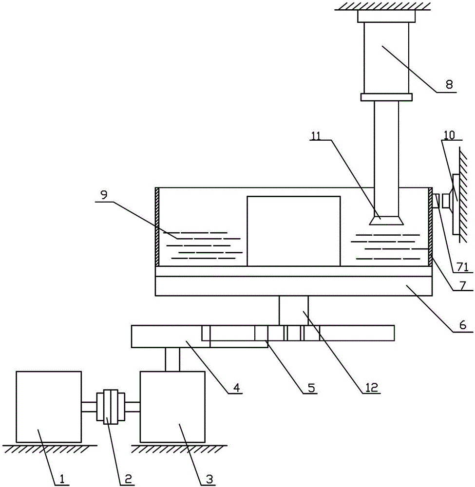
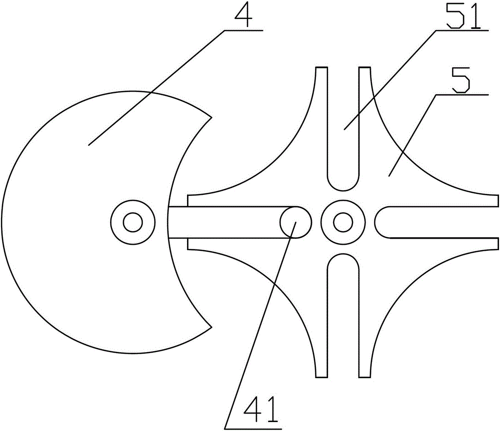
[0012] figure 1 Shown is a kind of hammering machine, including motor 1, reducer 3 and coupling 2 connected to motor 1 and reducer 3, and also includes turntable 6 and barrel 7 placed on turntable 6 and rotating with it. The output shaft of the reducer 3 is connected to the driving dial 4, and the driving dial 4 is provided with a round pin 41 that can enter or break away from the radial groove 51 on the driven sheave 5, and drives the driven sheave 5 to rotate or stop. The driving dial 4 and the driven sheave 5 constitute a sheave mechanism; the turntable 6 is disc-shaped, and the driven wheel 5 is connected to the turntable 6 through a connecting shaft 12, the axis of the connecting shaft 12 is connected to the turntable 6 The axis of rotation is coaxial; the upper part of the barrel 7 is provided with a beating device. Wherein, described beating device is made up of driving mechanism 8 and pounding hammer 11, and the piston rod of described driving mechanism 8 links to eac...


PUM


Abstract

The invention discloses a hair beating machine which comprises a motor, a speed reducer and a coupler connected between the motor and the speed reducer. The machine further comprises a rotating disc and a material tube arranged on the rotating disc and rotating with the rotating disc. An output shaft of the speed reducer is connected with a driving poking disc. A round pin capable of entering or leaving a radial groove in a driven groove wheel is arranged on the driving poking disc to drive the driven groove wheel to rotate or stop, and the driving poking disc and the driven groove wheel form a groove wheel mechanism. The rotating disc is disc-like, the driven wheel is connected with the rotating disc through a connection shaft, and the axis of the connection shaft is coaxial with the rotating axis of the rotating disc. A beating device is arranged on the upper portion of the material tube. The hair beating machine is high in automation degree and reliable in work, reduces labor intensity of workers and greatly saves production cost.

Description

technical field [0001] The invention relates to a hair beating machine, which belongs to the technical field of washing and dyeing machinery. Background technique [0002] Before dyeing, the wool must go through the pre-clear water treatment process. When washing with clean water, it must be beaten with a hammer to reduce the tension of the wool, so that the dye can easily enter it and enhance the dyeing performance. At present, some woolen mills of small and medium-sized enterprises in China still use primitive methods such as handwork for beating wool, or make some simple equipment by themselves, resulting in high labor costs. Contents of the invention [0003] The object of the present invention is to provide a hair beating machine aiming at the defects in the prior art. [0004] In order to achieve the above object, the present invention adopts the following technical solutions: a hair-beating machine, including a motor, a reducer and a coupling connected to the motor...

Claims


Application Information

Patent Timeline
Patent Type & Authority Patents(China)
IPC IPC(8): D06B23/00
Inventor 黄淑琴
Owner ZAOZHUANG CHEZHIJIE AUTOMOBILE EQUIP TECH CO LTD
Why Eureka
Try Eureka