
Friction clutch

A friction clutch and friction surface technology, applied in the field of parts, can solve the problems of increased cost, large volume and large diameter of friction clutch, and achieve the effect of reducing volume, reducing cost and increasing friction area

Inactive Publication Date: 2014-06-18
杨勇
View PDF8 Cites 0 Cited by
  • Summary
  • Abstract
  • Description
  • Claims
  • Application Information

AI Technical Summary

Problems solved by technology

[0011] The friction surfaces of the existing friction clutches are all flat. To achieve a sufficiently large friction force, the friction area must be increased. Therefore, the diameter of the existing friction clutches is relatively large, resulting in a relatively large volume of the friction clutch, which increases the cost.

Method used


Image

  • Friction clutch
  • Friction clutch
  • Friction clutch

Examples


Embodiment Construction

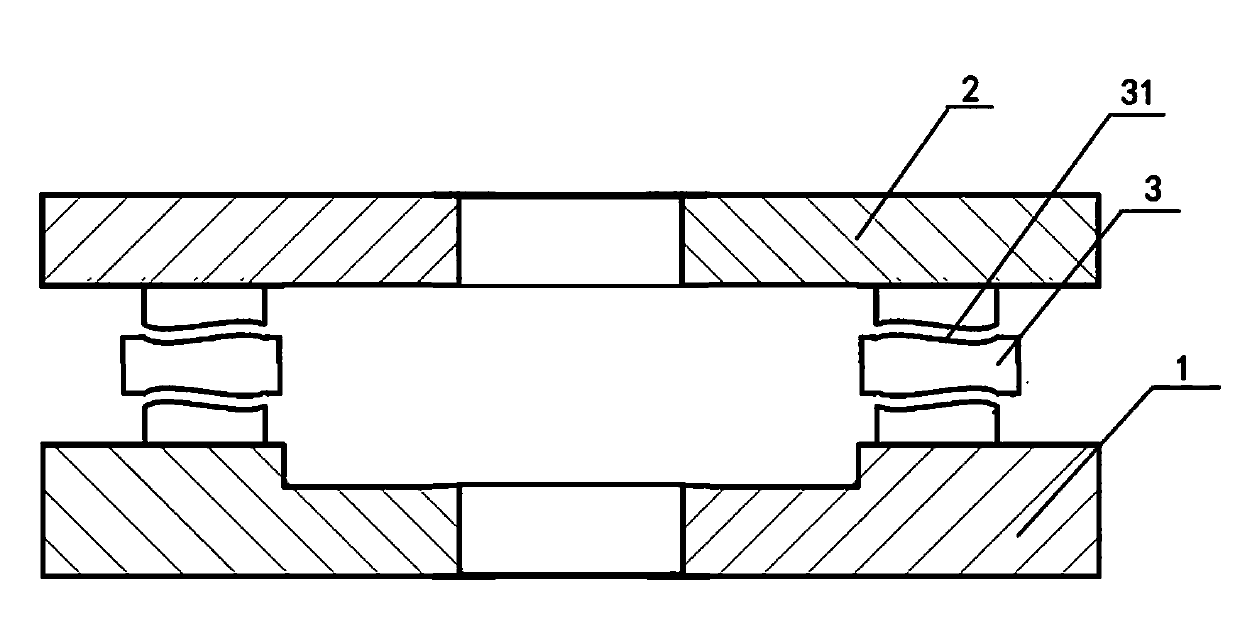
[0027] Such as Figure 1-4 A friction clutch, comprising a flywheel 1 and a pressure plate 2 of the active part, a driven plate 3 of the driven part, at least one annular groove is arranged on the friction surface of the driven plate 3, and the friction surface of the pressure plate and the flywheel is a The matching surface of the shaped groove.

[0028] Such as figure 1 In the friction clutch, the annular groove is an annular curved groove 31, and the friction surface of the pressure plate and the flywheel is an annular curved rib matching the annular curved groove.

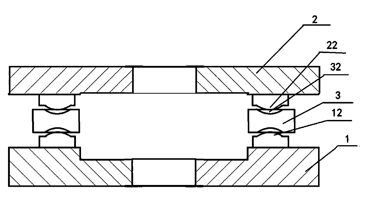
[0029] Such as figure 2 In the friction clutch, the annular curved surface groove is an annular arc groove 32, the friction surface of the pressure plate is an annular arc convex rib surface 22 matched with the annular arc groove, and the friction of the flywheel The surface is an annular arc ribbed surface 12 matched with the annular arc groove.

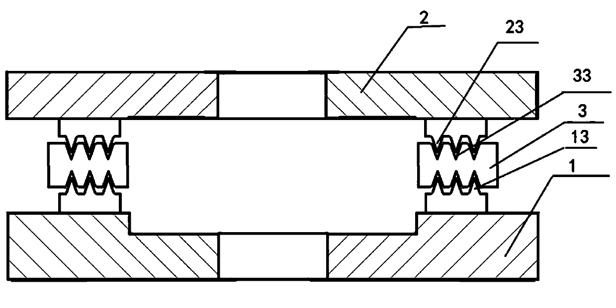
[0030] Such as image 3 In the friction clutch, the annul...


PUM


Abstract

Disclosed is a friction clutch. The friction clutch comprises a driving part including a flywheel and a pressing disc, and a driven part including and a driven disc. The friction surface of the driven disc is provided with at least one ring groove, and the friction surfaces of the pressing disc and the flywheel are matched with the ring grooves. According to the friction clutch, the grooves arranged in the friction surfaces enlarge the friction area and omit large treading force or large oil pressure; large friction force can be generated without the friction a large-diameter pressing disc, so that the size and the cost of the friction clutch can be reduced. For ring V-shaped grooves matched with ring V-shaped ribs, when the ring V-shaped grooves and the ring V-shaped ribs are completely close to each other, namely, provided with the same included angle, due to the facts that the average width of the V-shaped ribs is slightly larger than that of the V-shaped grooves and the top end of every V-shaped rib is in an arc shape, the grooves can generate large clamping force once the V-shaped ribs move forwards a little, and accordingly the friction force can be effectively transmitted, and the size and the cost of the friction clutch can be further reduced; the same is true for ring trapezoid ribs matched with ring trapezoid grooves.

Description

technical field [0001] The invention relates to a component directly connected with an engine in an automobile transmission system, specifically, a friction clutch. Background technique [0002] The clutch is responsible for the cut-off and combination of the power and the transmission system, so it can ensure the smooth start of the car when starting, the smooth shifting of gears, and prevent the transmission system from being overloaded. [0003] The clutch is used to cut and engage the power of the engine. The clutch is a transmission mechanism. It has an active part and a driven part. The two parts can be temporarily separated or slowly combined, and there may be relative rotation during the transmission process. Therefore, between the active part and the driven part of the clutch It will rely on contact friction to transmit torque, or use the pressing force required by friction to transmit torque. [0004] What is widely used in automobiles at present is exactly the f...

Claims


Application Information

Patent Timeline
IPC IPC(8): F16D13/00F16D13/14
Inventor 杨勇
Owner 杨勇
Features
  • Generate Ideas
  • Intellectual Property
  • Life Sciences
  • Materials
  • Tech Scout
  • Unparalleled Data Quality
  • Higher Quality Content
  • 60% Fewer Hallucinations
Learn More