
Deep sea pneumatic control valve

A pneumatic control valve, deep-sea technology, applied in diaphragm valves, valve devices, engine components, etc., can solve problems such as energy leakage, valves that cannot be opened normally, and environmental pollution

Inactive Publication Date: 2014-06-18
陈久挺
View PDF7 Cites 1 Cited by
  • Summary
  • Abstract
  • Description
  • Claims
  • Application Information

AI Technical Summary

Problems solved by technology

[0002] The traditional valve is mainly composed of a valve body, a bonnet, a medium inlet channel, a medium outflow channel, and a connecting cavity connecting the medium inlet channel and the medium outflow channel on the valve body. Sealing seat, there is a valve core that can seal with the sealing seat in the connecting cavity; usually, the opening of the valve core needs to be driven by the valve stem and the driving mechanism that drives the valve stem, such as an electric actuator or a handwheel to drive the valve core, so that Only when the valve core and the sealing seat are in contact and sealed can the conduction of the medium inlet channel and the medium outflow channel on the valve body be implemented (that is, the valve body is in the open state). However, when the valve body is in a special working condition, such as the seabed, due to The pressure on the seabed prevents the valve from opening normally. For example, the process of opening or closing it manually is cumbersome, and the process of opening or closing it is slow and time-consuming. When an emergency occurs in the seabed pipeline, The valve cannot be closed in time, causing energy leakage and polluting the environment

Method used


Image

  • Deep sea pneumatic control valve
  • Deep sea pneumatic control valve
  • Deep sea pneumatic control valve

Examples


Embodiment Construction

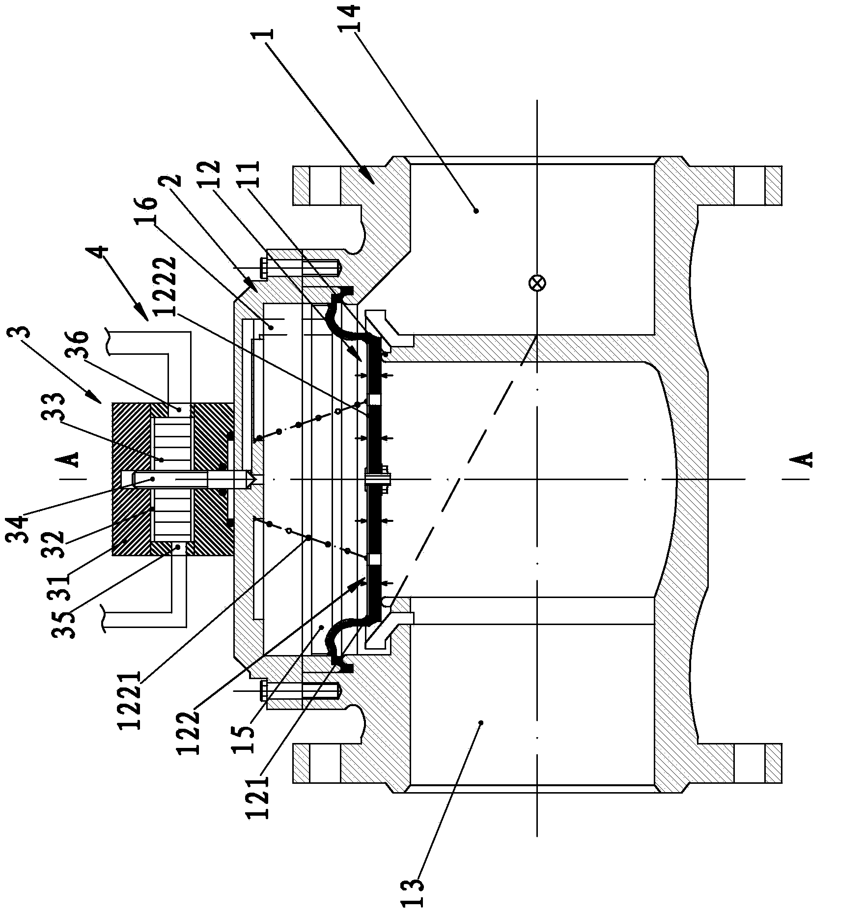
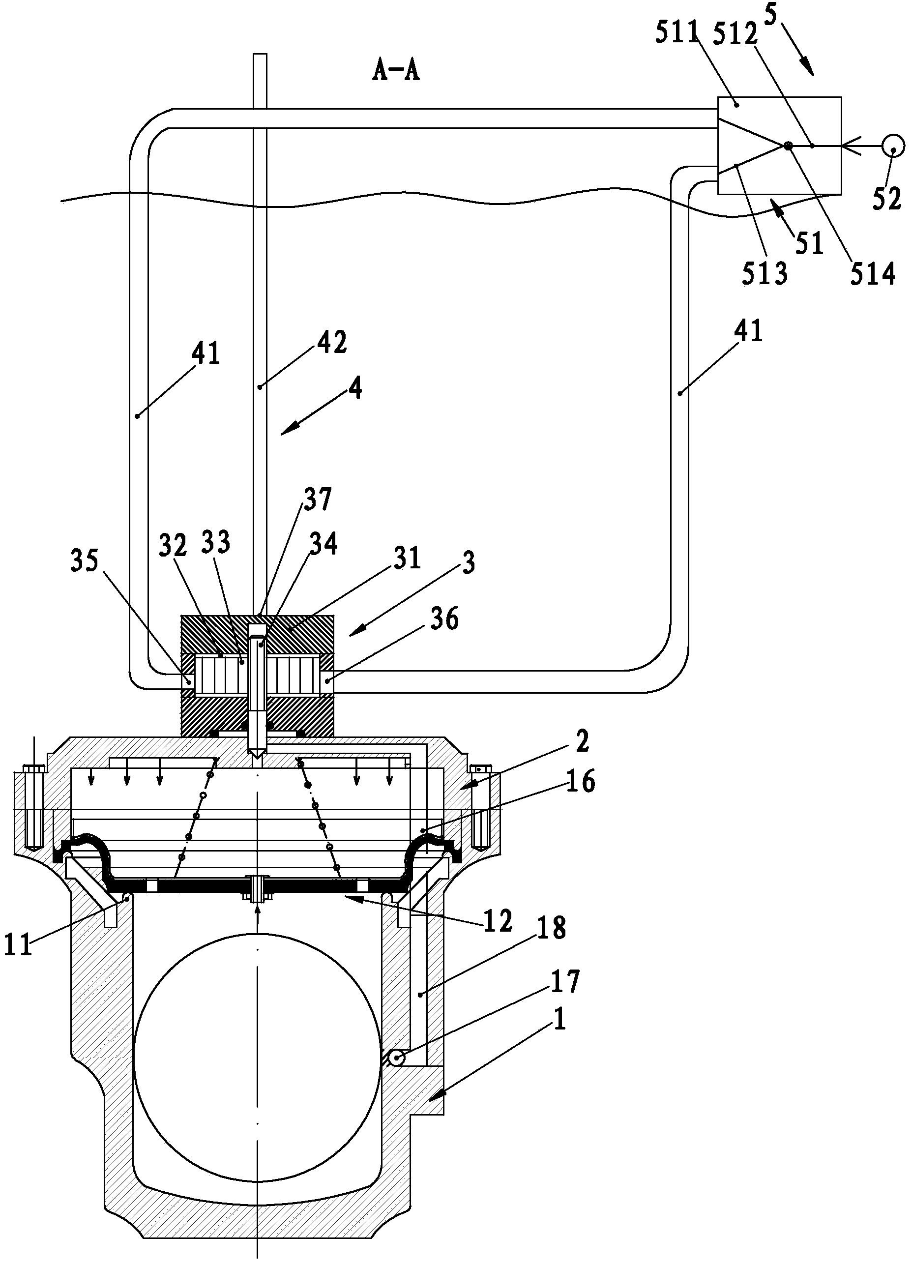
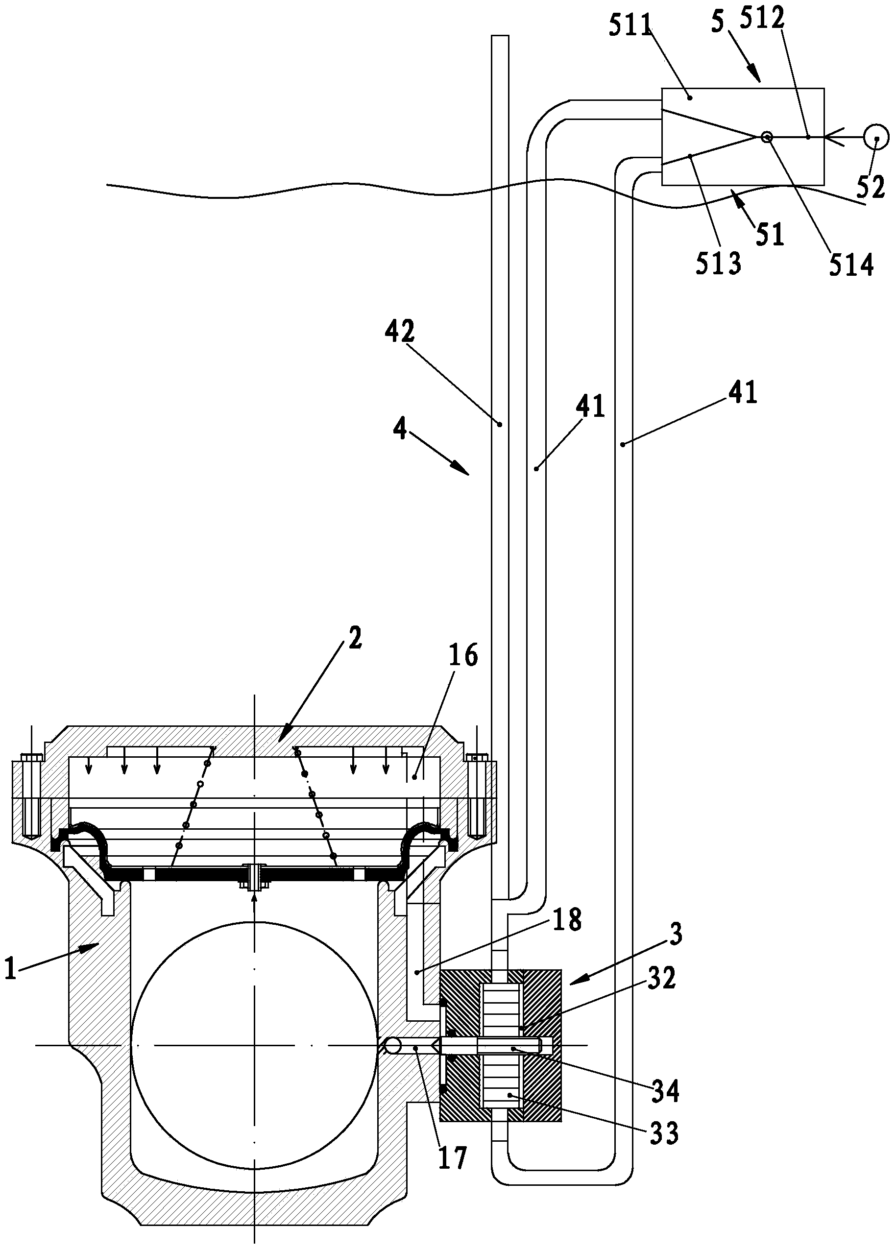
[0017] Such as figure 1 — Figure 5 A deep-sea pneumatic control valve shown includes a valve body 1 and a valve cover 2. The valve body 1 is provided with a valve channel, a valve seat 11 and a valve core 12. The valve channel includes a medium inlet channel 13 and a medium outflow channel 14. Between the valve cover 2 and the valve body 1, there is a connection cavity 15 for the medium inlet channel 13 and the medium outflow channel 14 to conduct. The conduction or closure of the channel 14; the valve body 1 is provided with a flow guide channel 16 connected with the connection chamber 15 and a pressure relief channel 17 connected with or closed with the flow guide channel 16, and one end of the pressure relief channel 17 is connected to the The chamber 18 communicates with the guide channel 16, and the other end communicates with the medium inlet channel 13 or the medium outflow channel 14 of the valve body 1. The transition chamber 18 is provided with a valve to promote t...


PUM


Abstract

The invention relates to a valve, in particular to a deep sea pneumatic control valve. The specific technical scheme is that the deep sea pneumatic control valve comprises a valve body and a bonnet, a valve passage, a valve seat and a valve core are arranged in the valve body, the valve passage comprises a medium inlet passage and a medium outlet passage, a connecting chamber for communicating the medium inlet passage and the medium outlet passage is arranged between the bonnet and the valve body, a guide passage which is communicated with the connecting chamber and a pressure relief passage which is communicated with or isolated from the guide passage are arranged on the valve body, one end of the pressure relief passage is communicated with the guide passage through an adapting chamber, the other end of the pressure relief passage is communicated with the medium inlet passage of the valve body, a micro control mechanism which enables the pressure relief passage to be communicated with or isolated from the guide passage is arranged in the adapting chamber, and one end, opposite to the other end which is connected with the pressure relief passage, of the micro control mechanism, is linked with a pneumatic regulation and control mechanism above the seal level through a connecting piece. By adopting the technical scheme, the deep sea pneumatic control valve provided by the invention has the advantages that the deep sea pneumatic control valve can be used for conveniently opening and closing a seabed pipeline and the structure is simple.

Description

technical field [0001] The invention relates to a valve, in particular to a deep sea pneumatic control valve. Background technique [0002] The traditional valve is mainly composed of a valve body, a bonnet, a medium inlet channel, a medium outflow channel, and a connecting cavity connecting the medium inlet channel and the medium outflow channel on the valve body. Sealing seat, there is a valve core that can seal with the sealing seat in the connecting cavity; usually, the opening of the valve core needs to be driven by the valve stem and the driving mechanism that drives the valve stem, such as an electric actuator or a handwheel to drive the valve core, so that Only when the valve core and the sealing seat are in contact and sealed can the conduction of the medium inlet channel and the medium outflow channel on the valve body be implemented (that is, the valve body is in the open state). However, when the valve body is in a special working condition, such as the seabed, d...

Claims


Application Information

Patent Timeline
IPC IPC(8): F16K7/17
CPCF16K7/17
Inventor 陈久挺
Owner 陈久挺
Learn More