A kind of led bulb lamp

A technology of LED bulb lamps and lamp holders, applied in the field of lighting, can solve the problems of low assembly efficiency, unfavorable market competition, and LED non-luminescence, etc., and achieve the effects of avoiding light blocking, good lighting effects, and large lighting angles

Inactive Publication Date: 2017-12-29
台州天瑞电器有限公司
View PDF7 Cites 0 Cited by
  • Summary
  • Abstract
  • Description
  • Claims
  • Application Information

AI Technical Summary

Problems solved by technology

However, when assembling this type of lamp holder, it is necessary to insert the conductive wire into the fixing hole, and then use the conductive cap to position the conductive wire. The assembly process is cumbersome, and the assembly efficiency is still low, which is not conducive to market competition.
Moreover, the existing LED bulb lamps are generally 120-degree light bulbs. This bulb lamp is to mount the LED on the plane of the radiator. Small problem, the light does not reach the place below the heat dissipation plane, it is easy to reverse the positive and negative poles when assembling the LED, which can easily cause the LED not to emit light, and the pass rate is low

Method used


Image

  • A kind of led bulb lamp
  • A kind of led bulb lamp
  • A kind of led bulb lamp

Examples


Embodiment Construction

[0027] The following are specific embodiments of the present invention in conjunction with the accompanying drawings to further describe the technical solutions of the present invention, but the present invention is not limited to these embodiments.

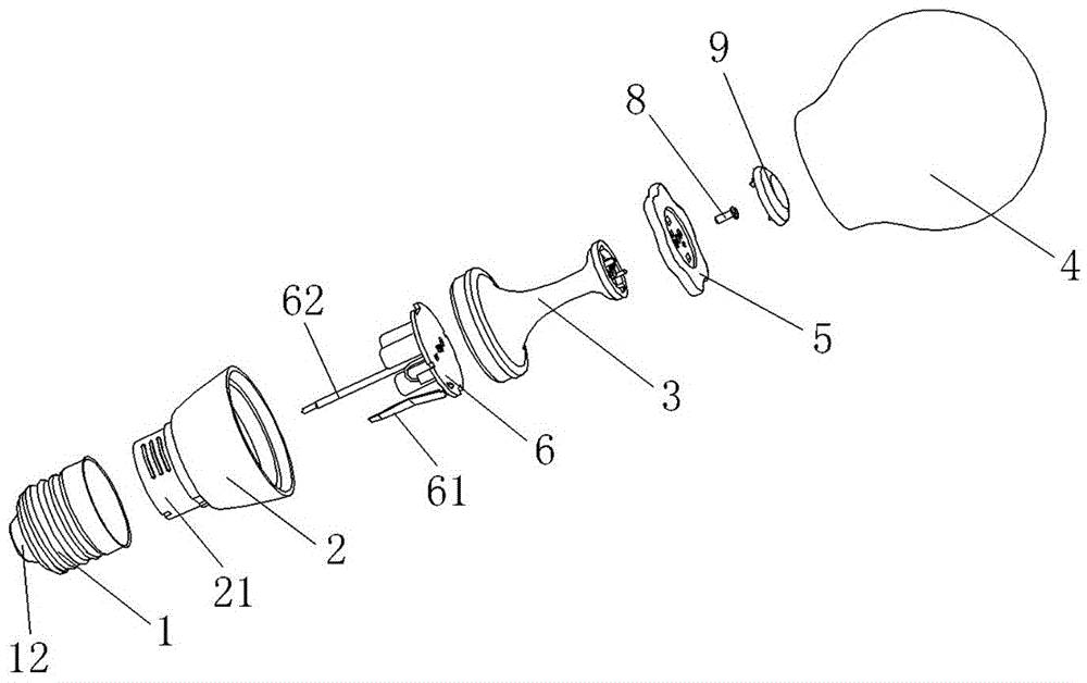
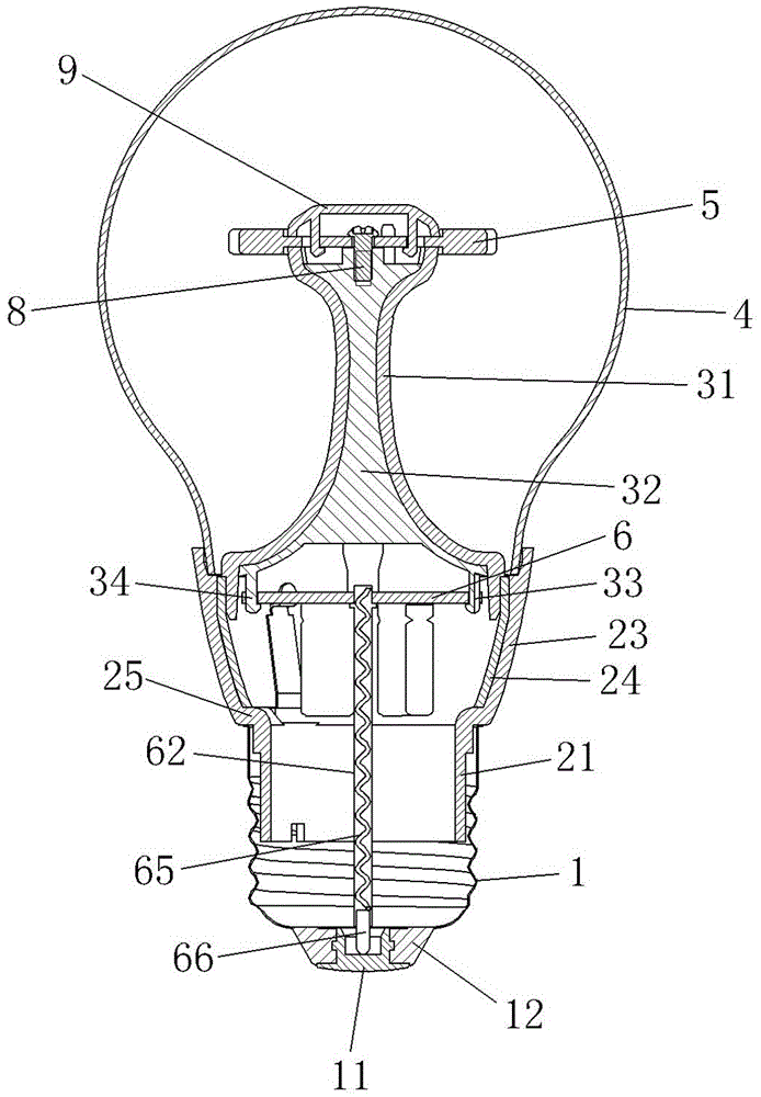
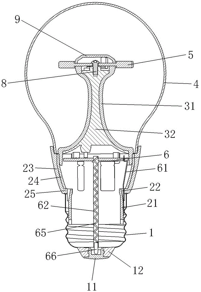
[0028] Such as figure 1 The LED bulb lamp shown includes a lamp cap 1, a heat sink with a connecting portion 21, a heat conduction module 3 arranged at the front of the heat sink 2, and a spherical transparent cover 4, such as figure 2 As shown, the tail of the lamp holder 1 is provided with a metal piece 11 and an insulator 12 for separating the metal piece 11 from the lamp holder 1. The front part of the lamp holder 1 is sleeved on the connecting part 21, and the front end of the heat conducting module 3 is provided with a transparent The double-sided COB light source 5 in the mask 4, such as Figure 4 As shown, the heat conduction module 3 is provided with a driving module 6 and wires for connecting the double-sided COB light sour...


PUM


Abstract

The invention provides an LED bulb lamp, and belongs to the technical field of lighting. The LED bulb lamp solves the problems that an existing LED bulb lamp is not convenient to assemble and small in luminous range. The LED bulb lamp comprises a lamp cap, a heat sink, a heat conduction module and a spherical light-transmitting cover, a metal piece and an insulator are arranged on the tail of the lamp cap, a connecting part is sleeved with the front of the lamp cap, the front end of the heat conduction module is provided with a two-sided COB light source which is located inside the light-transmitting cover, a drive module and a wire used for being connected with the two-sided COB light source and the drive module are arranged inside the heat conduction module, a through hole located in the inner side of the lamp cap is formed in the heat sink, the edge of the drive module is fixedly connected with an electricity-conducting elastic piece, one end of the electricity-conducting elastic piece penetrates through the through hole and extends to the position between the lamp cap and the connecting part, one side of the electricity-conducting elastic piece abuts against the connecting part, the other side of the electricity-conducting elastic piece abuts against the lamp cap, an elastic electricity-conducting needle is further arranged in the middle of the drive module, and one end of the elastic electricity-conducting needle abuts against the metal piece. The LED bulb lamp has the advantages of being convenient to assemble, wide in luminous range and the like.

Description

Technical field [0001] The invention belongs to the technical field of lighting and relates to an LED bulb lamp. Background technique [0002] As we all know, the lamp holder is used as a connecting part between the bulb and the lamp holder. Whether the traditional lamp holder is a screw-type or a bayonet-type lamp holder, the conductive wire is fixed to the conductive cap by soldering to form an electrical connection. However, the high cost of soldering, inconvenient operation, low assembly efficiency, and environmental pollution during the soldering process, obviously do not meet today's demand for environmental protection. At present, there are still some improved lamp caps on the market, which use a pin-shaped conductive cap to directly squeeze and fix the conductive wire. This squeeze-fixed connection method is more convenient and environmentally friendly than the traditional solder connection method. However, in actual production and assembly, it is found that its own stru...

Claims


Application Information

Patent Timeline
Patent Type & Authority Patents(China)
IPC IPC(8): F21K9/232F21V29/70F21V23/06F21Y115/10
Inventor 周益民
Owner 台州天瑞电器有限公司
Why Eureka
Try Eureka