Prism light guide mechanism for optical lens barrel and visual optical axis indication system

An optical lens barrel and prism technology, which is applied in the field of prism light guide mechanism and visual optical axis indication system, can solve the problems of affecting the experimental effect, large randomness, and quantitative control, so as to improve the experimental efficiency, reduce the experimental error, Avoid over-rotation effects

Pending Publication Date: 2020-07-28
XI'AN INST OF OPTICS & FINE MECHANICS - CHINESE ACAD OF SCI
View PDF0 Cites 0 Cited by
  • Summary
  • Abstract
  • Description
  • Claims
  • Application Information

AI Technical Summary

Problems solved by technology

[0003] The present invention aims to solve the problem that the pointing laser existing in the prior art cannot be positioned reliably, that is, it cannot be quantitatively controlled, which leads to greater randomness of the experiment and low efficiency of the experiment, especially when the pointing laser When internal reflection is required, there will be light blocking phenomenon, which seriously affects the technical problems of the experimental effect, and a prism light guide mechanism and a visual optical axis indication system for optical lens barrels are provided

Method used


Image

  • Prism light guide mechanism for optical lens barrel and visual optical axis indication system
  • Prism light guide mechanism for optical lens barrel and visual optical axis indication system
  • Prism light guide mechanism for optical lens barrel and visual optical axis indication system

Examples


Embodiment 1

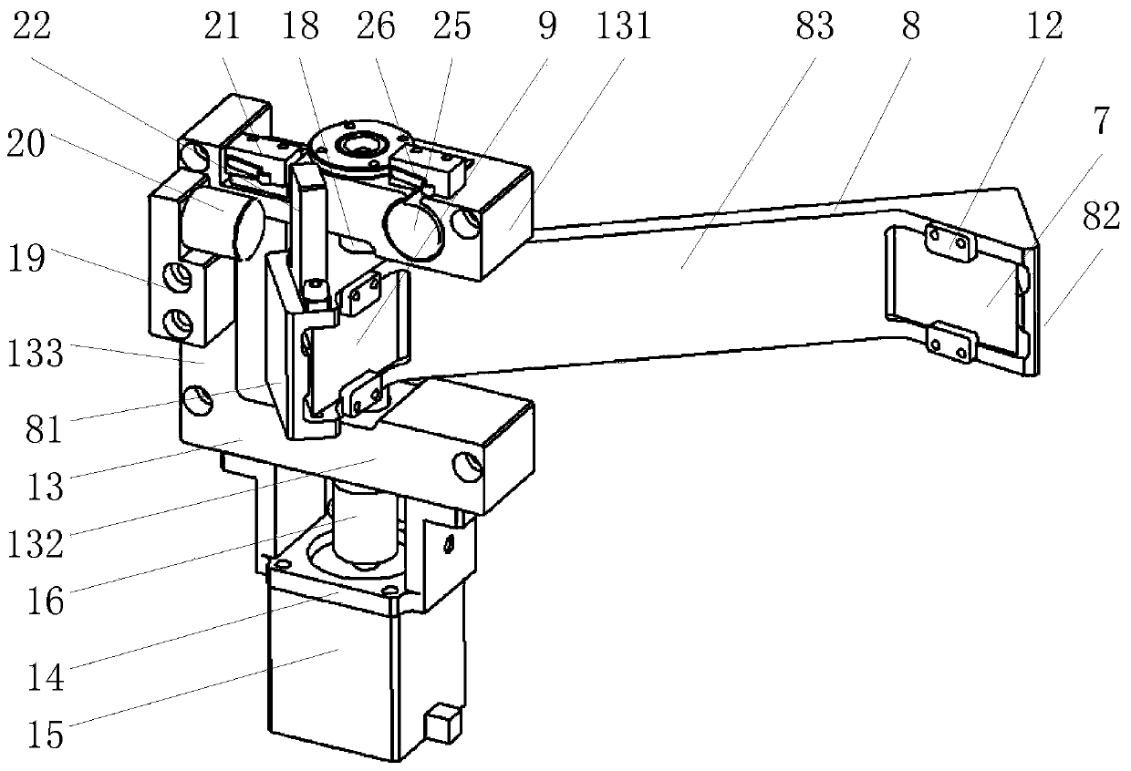
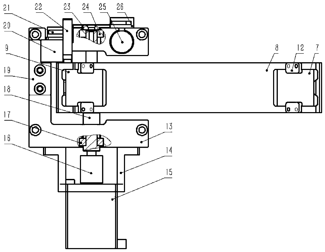
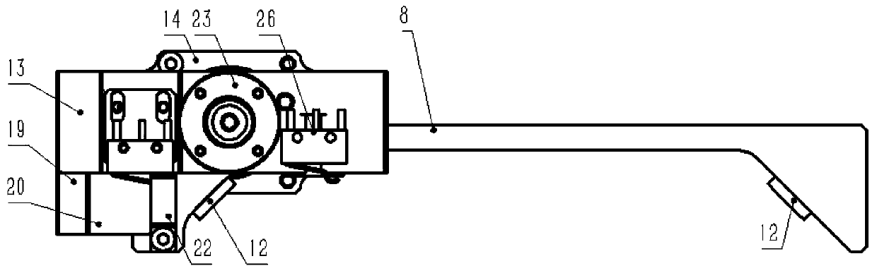
[0055] A prism light guide mechanism for optical lens barrel, such as figure 1 As shown, it includes a reflector group mount 13, a prism mount 8 and a rotating motor 15;

[0056] Such as figure 2 As shown, the reflector group mount 13 includes a first parallel plate 131 and a second parallel plate 132 parallel to each other, and a vertical plate 133 arranged at one end of the first parallel plate 131 and the second parallel plate 132; the first parallel plate 131 A rotating shaft 18 is arranged between the second parallel plate 132; the rotating shaft 18 is rotatably connected with the first parallel plate 131 through the rear bearing 24 to reduce the frictional force of rotation. The outer side of the first parallel plate 131 is provided with the rear bearing 24 Cooperating bearing end cover 23; rotatably connected with the second parallel plate 132 through the front bearing 17; the second parallel plate 132 is provided with a motor mounting frame 14; the rotating motor 15 ...

Embodiment 2

[0063] A visual optical axis indication system for optical barrels, combined with Figure 5 , Image 6 As shown, it can be used to indicate an optical lens 1. The optical lens 1 is provided with an optical lens barrel 2, and the inner wall of the rear end of the optical lens barrel 2 is provided with a second substrate; The optical pinhole 3 corresponds to the central optical axis 10 of the optical lens barrel 2; the outer wall of the optical lens barrel 2 is sequentially provided with a laser 5, a first substrate and a prism light guide mechanism as in Embodiment 1; wherein the laser 5 It is a point laser, and the laser 5 is arranged on the outer wall of the optical lens barrel 2 through the laser mounting seat 4; the wall of the optical lens barrel 2 between the first substrate and the prism light guide mechanism is provided with a prism mounting frame 8 cut into or Through the cut out hole, the prism light guide mechanism is installed on the optical lens barrel 2 through t...


PUM


Abstract

The invention discloses a prism light guide mechanism for an optical lens barrel and a visual optical axis indication system. The objective of the invention is to solve the problem that an indicationlaser cannot be reliably positioned, namely the quantitative control cannot be carried out, the randomness of the experiment is relatively high, the experiment efficiency is low, particularly, when the indication laser needs to be internally reflected, a light blocking phenomenon also occurs, and the experiment effect is seriously influenced. The indication laser outside the optical lens barrel can be guided into the central optical axis inside the optical lens barrel through the interaction of a reflecting light prism and an incident light prism of which the mirror surfaces are opposite and the included angle is 90 degrees, and the central optical axis of the optical lens barrel is calibrated through the external indication laser, so that reliable positioning of the central optical axis is realized, experiment errors are reduced, experiment randomness is reduced, and experiment efficiency is improved.

Description

technical field [0001] The invention relates to an optical lens barrel, in particular to a prism light guide mechanism and a visual optical axis indicating system for the optical lens barrel. Background technique [0002] In optical experiments, when the optical axis of the optical path is aligned and the recording medium is placed, it is often necessary to fine-tune the light source to realize the alignment and aiming process. In the prior art, an external pointing laser is basically used to indicate the optical axis, so as to achieve alignment and alignment Yes, but the existing pointing laser cannot be positioned reliably, that is, it cannot be quantitatively controlled, which leads to a large randomness of the experiment and causes problems such as low experimental efficiency. More importantly, when the pointing laser needs to be reflected internally, there is still the problem of light blocking, which seriously affects the experimental results. Contents of the inventi...

Claims


Application Information

Patent Timeline
Patent Type & Authority Applications(China)
IPC IPC(8): G02B27/00G02B7/18G02B7/182G02B7/00
CPCG02B27/00G02B7/1805G02B7/182G02B7/003
Inventor 李奇王军宁闫亚东薛艳博张敏何俊华
Owner XI'AN INST OF OPTICS & FINE MECHANICS - CHINESE ACAD OF SCI
Why Eureka
Try Eureka