
Cursor moving method and oscilloscope

A technology of cursor movement and oscilloscope, which is applied to instruments, digital variable/waveform display, measuring devices, etc. It can solve the problems of inaccurate cursor positioning and low efficiency, and achieve the effects of simplifying operations, reducing adjustment time, and improving efficiency

Active Publication Date: 2014-06-18
RIGOL
View PDF6 Cites 3 Cited by
  • Summary
  • Abstract
  • Description
  • Claims
  • Application Information

AI Technical Summary

Problems solved by technology

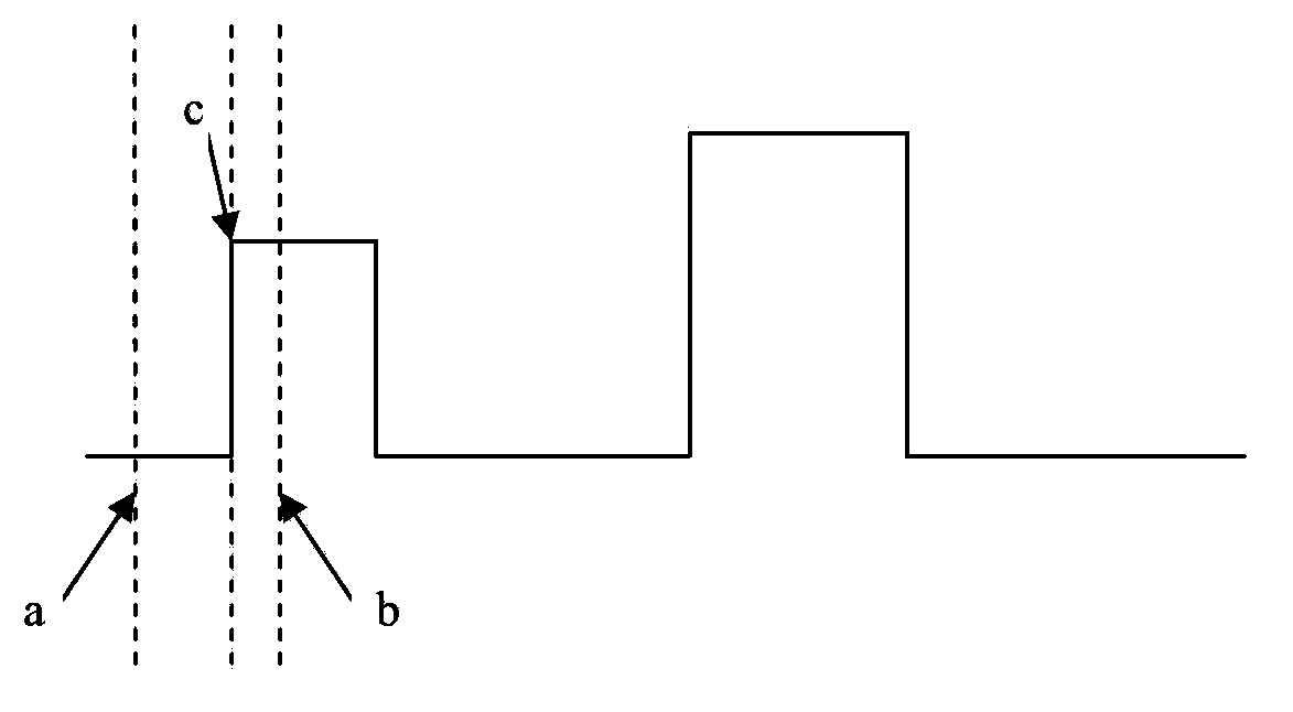
[0012] The embodiment of the present invention is to solve a cursor moving method and an oscilloscope in the prior art, and is used to solve the problem of inaccurate positioning and low efficiency of adjusting the cursor of the oscilloscope in the prior art

Method used


Image

  • Cursor moving method and oscilloscope
  • Cursor moving method and oscilloscope
  • Cursor moving method and oscilloscope

Examples


Embodiment Construction

[0054] In order to make the purpose, technical solutions and advantages of the embodiments of the present invention more clear, the embodiments of the present invention will be further described in detail below in conjunction with the embodiments and the accompanying drawings. Here, the exemplary embodiments and descriptions of the present invention are used to explain the present invention, but not to limit the present invention.

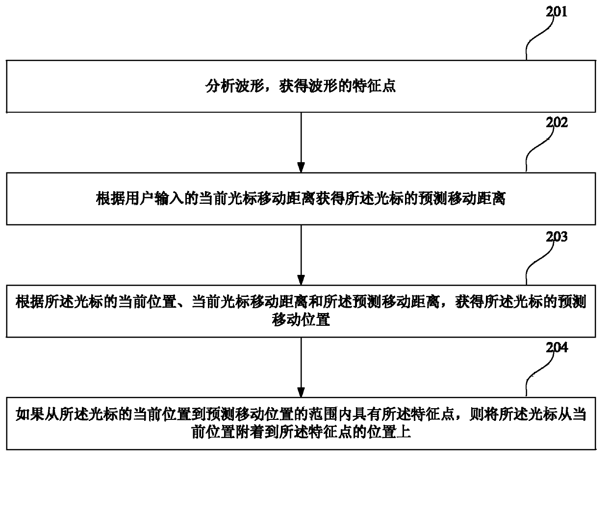
[0055] like figure 2 It is a flowchart of a method for moving a cursor provided by an embodiment of the present invention.

[0056] Including step 201, analyzing the waveform to obtain the characteristic points of the waveform.

[0057]Wherein, the characteristic points of the obtained waveform include edge positions, zero-crossing points, etc. in the horizontal direction, and peak-to-peak values, maximum or minimum values ​​in the vertical direction. According to different waveforms, the feature points are not the same, and some feature point s...


PUM


Abstract

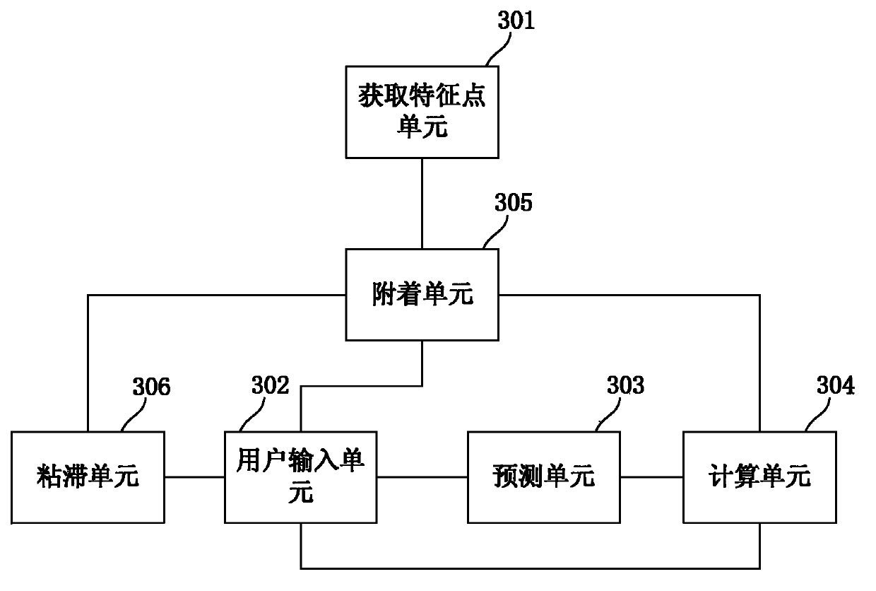
The invention relates to the test measurement technical field, and especially relates to a cursor moving method and an oscilloscope; the method comprises the following steps: obtaining a present cursor moving distance according to a cursor moving instruction, and obtaining a prediction moving distance of the cursor according to the present cursor moving distance; obtaining the prediction moving distance of the cursor according to the present position of the cursor, the present cursor moving distance and the prediction moving distance; if a feature point is spotted in a scope between the present position of the cursor and a prediction moving position, then the cursor can be attached to the position of the feature point from the present position. By employing the method and the oscilloscope, the position of the cursor can be accurately controlled in a small operation interface of the oscilloscope, thereby simplifying user operation and improving waveform detection efficiency.

Description

technical field [0001] The invention relates to the technical field of test and measurement, in particular to a method for moving a cursor and an oscilloscope. Background technique [0002] Digital oscilloscopes can display the relationship of electrical signals with time. In applications, the two parameters of time and voltage are usually concerned, that is, the numerical characteristics in the horizontal and vertical dimensions. For example, the time difference in the horizontal direction, the voltage difference in the vertical direction, etc. [0003] For a captured signal, the user may need to analyze its detailed information to find out whether it is consistent with the design or whether the circuit is working in a normal state, so it is very important to analyze the waveform details. [0004] In many applications, users want to be able to intuitively read the time difference and amplitude difference of a waveform, and then obtain parameters such as frequency and perce...

Claims


Application Information

Patent Timeline
IPC IPC(8): G01R13/00
Inventor 王志彦王悦王铁军李维森
Owner RIGOL
Learn More