Method for determining shot point combination

A technology of shot point and shot point, which is applied in the field of determining shot point combination in seismic data acquisition, can solve the problems of effective diffracted wave field energy attenuation, affecting the quality of seismic migration imaging, unable to meet pre-stack migration imaging and other problems

Active Publication Date: 2014-06-18
BC P INC CHINA NAT PETROLEUM CORP +1
View PDF4 Cites 4 Cited by
  • Summary
  • Abstract
  • Description
  • Claims
  • Application Information

AI Technical Summary

Problems solved by technology

However, the current method of offset detection combination is based on the time change rate of two-dimensional reflected waves. This method only considers the suppression of noise by longitudinal combination, and does not consider the suppression of noise by combination in other directions, so it is not suitable for 3D seismic The requirements for the combination of data acquisition; the second is to determine the combined base distance according to the time rate of the reflected wave field at the maximum offset distance, and only consider the protection of the reflected signal without considering the influence of the effective diffraction wave field. The design is often too large, which will cause serious energy attenuation of the effective diffracted wave field, which cannot meet the requirements of pre-stack migration imaging and affect the quality of seismic migration imaging

Method used


Image

  • Method for determining shot point combination
  • Method for determining shot point combination
  • Method for determining shot point combination

Examples


Embodiment Construction

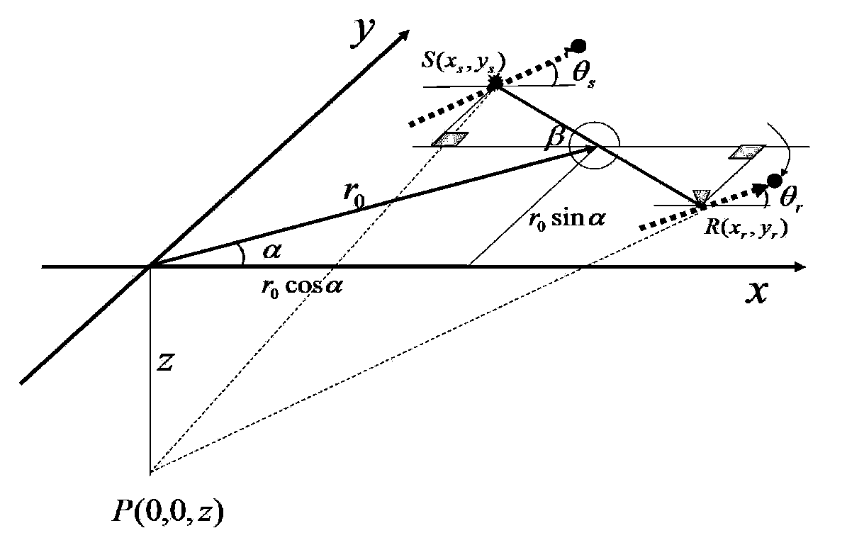
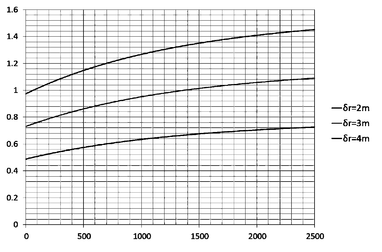
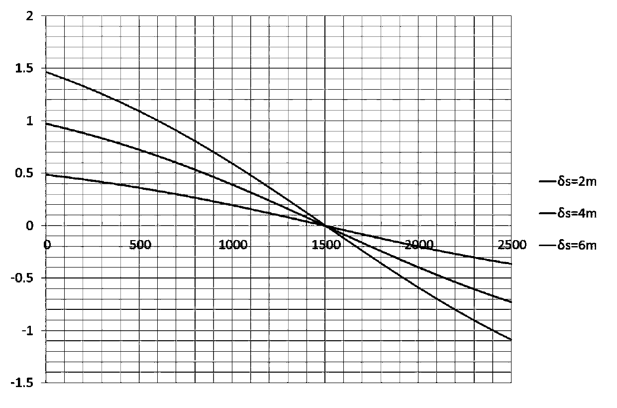
[0041] The core of the present invention is to start from the distribution characteristics of the point source diffraction wave field and according to the requirements of the pre-stack migration imaging for the protection of the diffraction wave field, determine the combined base distance of the shot point and the combined base distance of the receiver point in any direction.

[0042] The specific implementation steps are as follows:

[0043] 1) Collect previous seismic data and obtain geophysical parameters to determine the offset combination:

[0044] In step 1), the geophysical parameters for obtaining and determining the offset combination are:

[0045] Determine the depth of the target layer according to the seismic interpretation data and drilling data; select the depth of the diffraction point and the formation dip at the diffraction point according to the depth of the target layer;

[0046] Obtain the reflection time and stacking velocity of the target layer according...


PUM


Abstract

The invention relates to a method for determining a shot point combination in geophysical exploration seismic data acquisition. The method comprises the following steps: acquiring or collecting history seismic data; acquiring the geophysical parameters for determining the shot point combination; determining the diffracted wave field maximum time change rates of the inner distance of a shot point group and the inner distance of a detection point group; determining the maximum suppression characteristic curve of diffracted wave by the shot point combination; determining the shot point combination according to the maximum suppression characteristic curve of diffracted wave by the shot point combination. By adopting the method, the base distance of the shot point combination and the base distance of the detection point combination can be determined through the depth of an underground diffracting point, the root mean square speed of a rising stratum, an offset distance vector and a shot-geophone distance vector in combination with the maximum frequency (high cut-off frequency) of diffracted wave needing to the protected.

Description

technical field [0001] The invention relates to geophysical prospecting technology, and relates to a method for determining combination of shot-check points in seismic data acquisition. Background technique [0002] In seismic data acquisition, receiver point combination and shot point combination (shot detection combination) are commonly used to suppress noise and protect effective signals. However, the current method of offset detection combination is based on the time change rate of two-dimensional reflected waves. This method only considers the suppression of noise by longitudinal combination, and does not consider the suppression of noise by combination in other directions, so it is not suitable for 3D seismic The requirements for the combination of data acquisition; the second is to determine the combined base distance according to the time rate of the reflected wave field at the maximum offset distance, and only consider the protection of the reflected signal without ...

Claims


Application Information

Patent Timeline
Patent Type & Authority Applications(China)
IPC IPC(8): G01V1/20
Inventor 唐东磊蔡锡伟何永清宁宏晓
Owner BC P INC CHINA NAT PETROLEUM CORP
Why Eureka
Try Eureka