Axial flow fan

A technology of axial flow fan and diameter reducing part, which is applied to non-variable-capacity pumps, pumps, electrical components, etc., can solve problems such as troublesome cross-sectional shapes of conductive pins

Inactive Publication Date: 2014-06-18
SANYO DENKI CO LTD
View PDF5 Cites 8 Cited by
  • Summary
  • Abstract
  • Description
  • Claims
  • Application Information

AI Technical Summary

Problems solved by technology

However, even if the techniques of Patent Documents 1 and 2 are applied, troubles caused by the cross-sectional shape of the conductive pins will also occur.

Method used


Image

  • Axial flow fan
  • Axial flow fan
  • Axial flow fan

Examples


Embodiment Construction

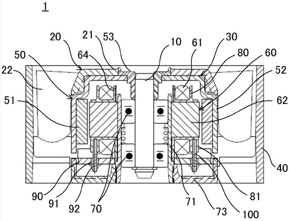
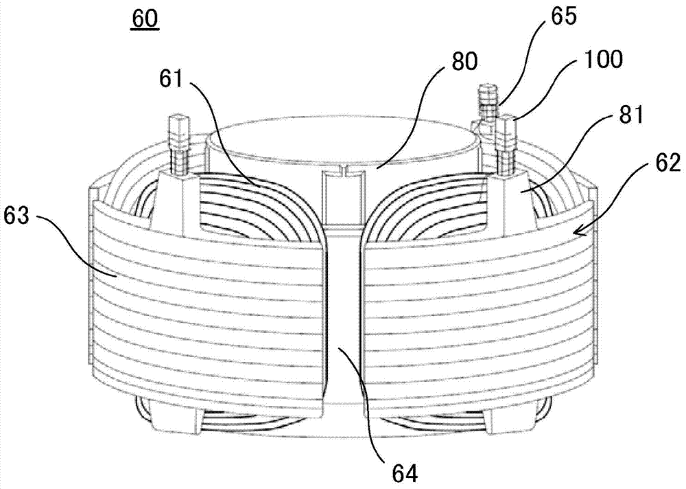
[0047] Next, an axial flow fan according to this embodiment will be described with reference to the drawings.

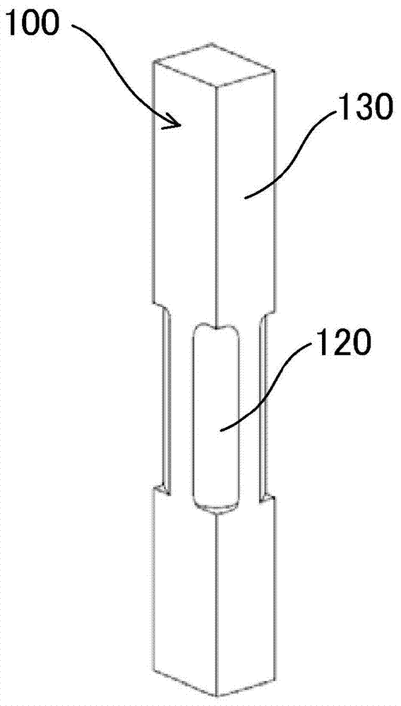
[0048] In the axial flow fan of this embodiment, the shape of the conductive pin is a square prism (square prism pin) as the basic shape, and at least a part of the exposed portion exposed from the electrical insulator has a reduced diameter portion that does not have the corners of the square prism pin. . According to this embodiment, it is possible to realize an axial flow fan having a conductive pin that can reliably hold the film wire of the coil, prevents disconnection even when an unexpected load is applied to the film wire, and can respond to the end of winding. Automatic cut-off of the membrane leads. It should be noted that, in this embodiment, although the basic shape of the conductive pin is set as a quadrangular prism with an internal angle of 90°, the basic shape of the conductive pin may also be a triangular prism with an internal angle of less than 90...


PUM


Abstract

The present invention provides an axial flow fan capable of reliably maintaining a film conductive line of the coil. Even when unexpected load is added to the film conductive line, fracture of the line can be prevented. The axial flow fan is provided with conductive pins capable of being automatically cut off corresponding to the film conductive line finishing winding. The conductive pin is configured to electrically connect a coil of a stator and a circuit board, and to hold a film conductive line of the coil. In the conductive pin, one end is fixed to an electrical insulator covering a core stack of the stator, and the other end is electrically connected to the circuit board. The conductive pin is a quadrangular prism pin as a basic configuration and has, in at least a part of a portion exposed from the electrical insulator, a reduced diameter portion having no corners.

Description

technical field [0001] The present invention relates to an axial flow fan which improves the structure of a conductor pin which electrically connects a coil and a circuit board and holds a film wire (coated wire) of the coil. Background technique [0002] In a small axial flow fan such as a cooling fan, an outer rotor type brushless motor is generally used as a rotational drive device for the impeller. The outer rotor type brushless motor has an armature having multi-phase coils as a stator, and an excitation part having permanent magnets is arranged on the outer periphery of the stator as a rotor. [0003] The winding start end and the winding end portion of the coils of each phase are electrically connected to the circuit board via conductive pins fixed to the insulator of the stator core. In addition, connecting wires (tori wires) for tying the coils together to form the coils of the respective phases are bundled and held by conductive pins. [0004] As a technique rela...

Claims


Application Information

Patent Timeline
Patent Type & Authority Applications(China)
IPC IPC(8): H02K3/46
CPCF04D13/06F04D25/0613F04D25/068F04D25/0693
Inventor 高桑宗仙洼田光孝
Owner SANYO DENKI CO LTD
Why Eureka
Try Eureka