Heat dissipation device

A heat dissipation device and body technology, applied in the direction of cooling/ventilation/heating transformation, etc., can solve the problems of inability to have remote heat dissipation effect, poor heat dissipation speed, narrow heat dissipation range, etc.

Inactive Publication Date: 2014-06-18
ASIA VITAL COMPONENTS SHENZHEN CO LTD
View PDF4 Cites 8 Cited by
  • Summary
  • Abstract
  • Description
  • Claims
  • Application Information

AI Technical Summary

Problems solved by technology

[0007] 1. There is no remote cooling effect;
[0008] 2. Narrow heat dissipation range;
[0009] 3. Poor cooling speed

Method used


Image

  • Heat dissipation device
  • Heat dissipation device
  • Heat dissipation device

Examples


Embodiment Construction

[0037] The above-mentioned purpose of the present invention and its structural and functional characteristics will be described according to the preferred embodiments of the accompanying drawings.

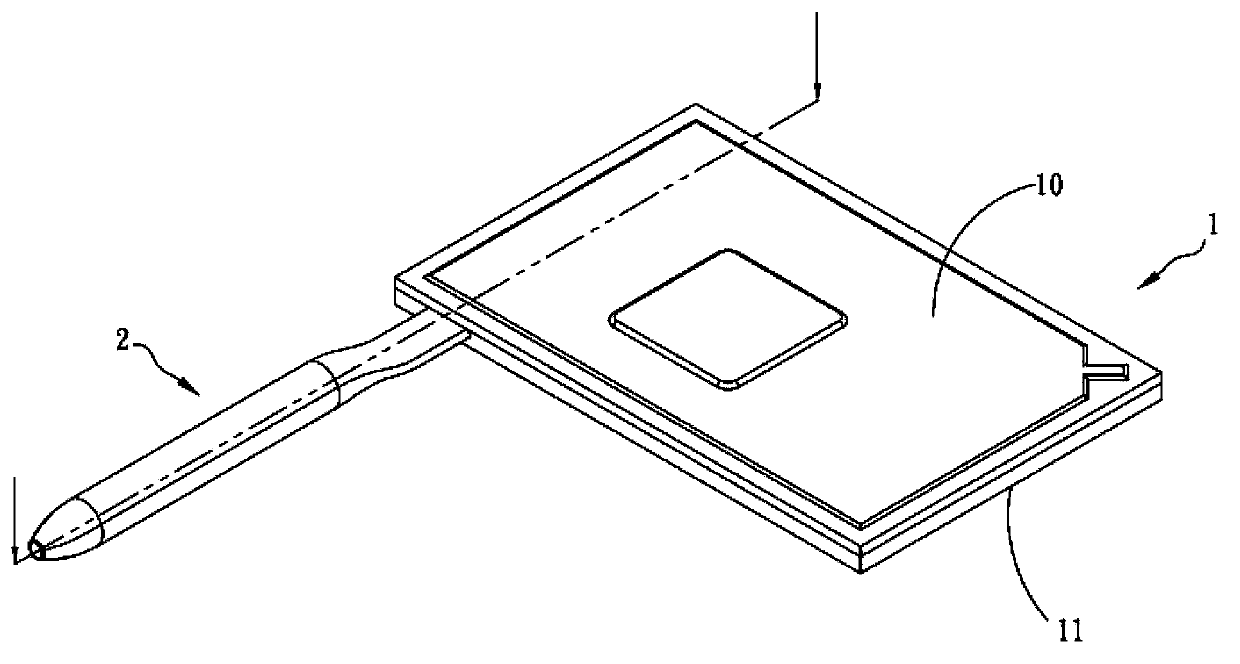
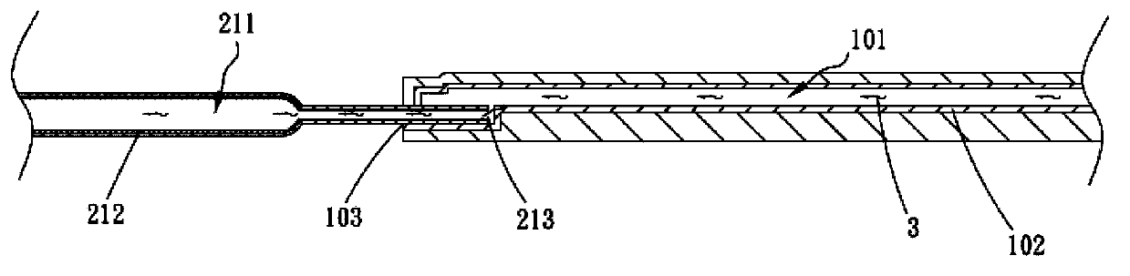
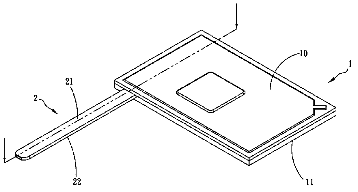
[0038] see Figure 1A , Figure 1B , is a three-dimensional combined view and a cross-sectional view of the first embodiment of the heat dissipation device of the present invention. A heat dissipation device includes a first body 1, a second body 2 and a working fluid 3. The first body 1 has a first Plate body 10 and a second plate body 11 relative to the first plate body 10, the first and second plate bodies 10, 11 correspond to the cover and jointly define a first chamber 101, the inner wall of the first chamber 101 is provided with There is a first capillary structure 102, the first capillary structure 102 can be any one of sintered powder body, grid body, fiber body, foam material and porous material, and the first body 1 also has an orifice 103;

[0039] The aforementioned s...


PUM


Abstract

A heat dissipation device comprises a first body, a second body, and working fluid. The first body comprises a first plate body and a second plate body corresponding to the first plate body, and the first plate body and the second plate body are shut together to jointly define a first chamber. The second body is connected with the first body and is provided with a second chamber communicated with the first chamber correspondingly. The working fluid is filled in the first and second chambers. Through the design of the structure and by the aid of the working fluid flowing inside the first and second chambers circularly, the heat dissipation device is enabled to have a far-end heat dissipation effect.

Description

technical field [0001] The invention relates to a heat dissipation device, in particular to a heat dissipation device with remote heat dissipation effect and increased heat dissipation range. Background technique [0002] With the rapid progress of the technology industry, the functions of electronic devices are becoming more and more powerful. For example, the computing speed of electronic components such as central processing unit (Central Processing Unit, CPU), chipset or display unit is also increasing, resulting in the unit time of electronic components The generated heat will be relatively increased; therefore, if the heat emitted by the electronic components cannot be dissipated in time, it will affect the overall operation of the electronic device or cause damage to the electronic components. [0003] Most of the electronic component cooling devices used in the industry dissipate heat through cooling elements such as fans, heat sinks, or heat pipes, and contact the h...

Claims


Application Information

Patent Timeline
Patent Type & Authority Applications(China)
IPC IPC(8): H05K7/20
Inventor 杨修维
Owner ASIA VITAL COMPONENTS SHENZHEN CO LTD
Why Eureka
Try Eureka