Upper transmission mechanism of automatic lacing machine

A transmission mechanism and automatic wearing technology, applied in footwear, shoe bindings, clothing, etc., can solve the problems of shoelace failure, high matching accuracy, and high cost of the driving mechanism, achieving accurate positioning, convenient feeding, simple structure

Active Publication Date: 2015-04-15
NINGBO SUPREME ELECTRONIC MASCH INC
View PDF4 Cites 0 Cited by
  • Summary
  • Abstract
  • Description
  • Claims
  • Application Information

AI Technical Summary

Problems solved by technology

[0004] Although the technical scheme disclosed in the above-mentioned patent can be used for wearing shoelaces, there are many defects.
For example, it is troublesome to unload the upper of the shoe; two sets of driving mechanisms, the front main arm and the rear main arm, are required to wear the shoelaces. The cost of the two sets of driving mechanisms is high, and the matching requirements are high. Once a mistake is made, it will lead to failure to wear the shoelaces.

Method used


Image

  • Upper transmission mechanism of automatic lacing machine
  • Upper transmission mechanism of automatic lacing machine
  • Upper transmission mechanism of automatic lacing machine

Examples


Embodiment Construction

[0027] Embodiments of the present invention will be described in further detail below in conjunction with the accompanying drawings.

[0028] Figure 1 to Figure 9 Shown is the structural representation of the present invention.

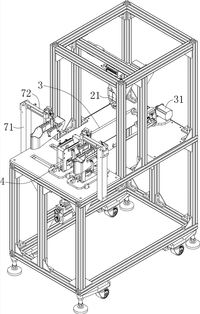
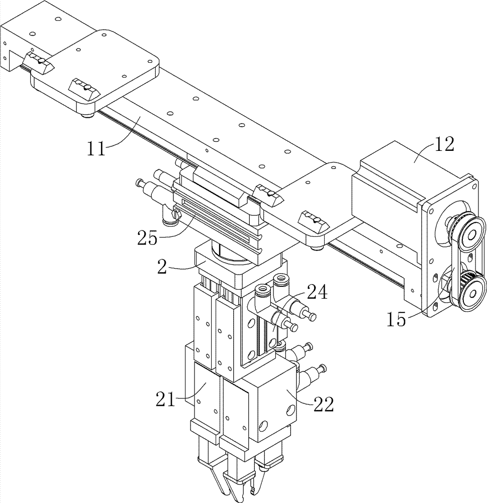
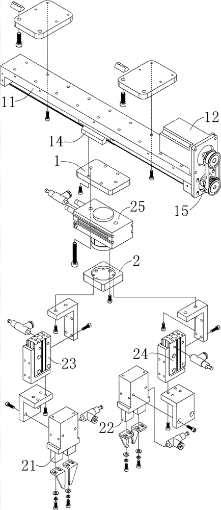
[0029] The automatic shoelace machine includes a clamp mounting base 1 capable of linear motion in the X direction, a rotating seat 2 capable of rotating motion is provided on the clamp mounting base 1, and a first lifting cylinder 23 is arranged on the rotating base 2. The first clamp 21 and the second clamp 22 driven by the second lift cylinder 24 . The first clamp 21 and the second clamp 22 can clamp the shoelace ends, and under the drive of the clamp mounting base 1, alternately clamp the shoelace ends and pass the shoelace ends through the shoelace holes on the upper.

[0030] Such as Figure 1 to Figure 3 As shown, the clamp mounting base 1 is located on the upper part of the frame, and has an X-direction driving motor 12 that drives the cla...


PUM


Abstract

The invention discloses an upper transmission mechanism of an automatic lacing machine. The upper transmission mechanism comprises a Y-direction connecting seat connected with an upper locating seat, and a Y-direction driving motor for driving the Y-direction connecting seat to make linear motion, wherein the Y-direction connecting seat can be connected or disconnected with the upper locating seat; the Y-direction driving motor is connected with the Y-direction connecting seat by a Y-direction transmission component. According to the upper transmission mechanism, an upper is fixed by the upper locating seat; the upper transmission mechanism has the advantages of being simple in structure, convenient in discharging and accurate in location; the upper is driven to move along a straight line by the upper locating seat which is driven by the Y-direction driving motor, and the upper is automatically matched with the work progress of a first fixture and a second fixture, so that shoe lace bundle heads can accurately pass through lace holes in sequence.

Description

technical field [0001] The invention relates to an automatic shoelace machine for threading shoelaces on shoe uppers, in particular to a shoe upper transmission mechanism of the automatic shoelace machine. Background technique [0002] In the production process of shoes, after the shoe processing is completed, a step of wearing shoelaces is required. At present, wearing shoelaces is all done manually by workers. Because the output of shoes is very large every year, it is very time-consuming to wear the shoelaces on the shoes, so this step wastes manpower and cost, and reduces the production efficiency of shoes. [0003] Invention patent application number: 201210310460.5, patent name An automatic shoelace machine discloses a device for shoelacing shoes during processing, including a machine frame, workbench X linear module, and workbench Y linear module , front mount, forearm X linear module, forearm Z linear module, front main arm, front gripper, rear mount, rear arm X li...

Claims


Application Information

Patent Timeline
Patent Type & Authority Patents(China)
IPC IPC(8): A43C7/00
Inventor 罗千
Owner NINGBO SUPREME ELECTRONIC MASCH INC
Why Eureka
Try Eureka