Edge strip die

A mold and side strip technology, which is applied in the field of side strip molds, can solve problems such as reverse installation and side strip mold crushing, and achieve the effects of preventing crushing, facilitating mold installation, and improving quality

Inactive Publication Date: 2014-06-25
昆山金九亿精密金属有限公司
View PDF3 Cites 0 Cited by
  • Summary
  • Abstract
  • Description
  • Claims
  • Application Information

AI Technical Summary

Problems solved by technology

[0003] In the existing side strip mould, it is often reversed when loading the mold, resulting in the side strip mold being crushed

Method used


Image

  • Edge strip die

Examples


Embodiment Construction

[0019] Embodiments of the present invention are described in detail below, examples of which are shown in the drawings, wherein the same or similar reference numerals designate the same or similar elements or elements having the same or similar functions throughout. The embodiments described below by referring to the figures are exemplary only for explaining the present invention and should not be construed as limiting the present invention.

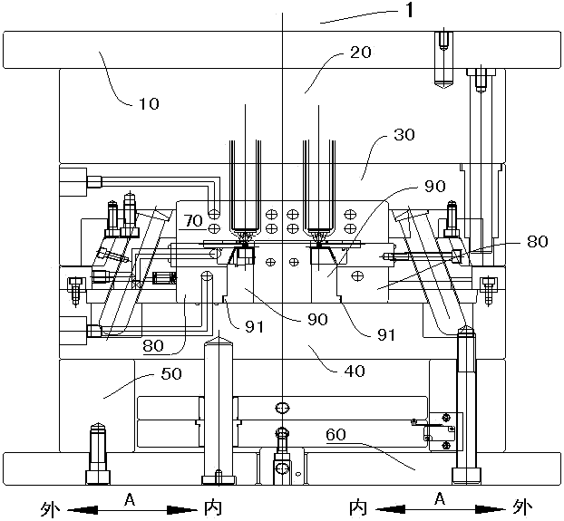
[0020] Refer below figure 1 The strip mold 1 according to the embodiment of the present invention is described. Such as figure 1 As shown, the edge strip mold 1 according to the embodiment of the present invention includes an upper runner plate 10 , a lower runner plate 20 , an upper mold plate 30 , a lower mold plate 40 , a lower insulation plate 50 , a bottom plate 60 , a splint 80 and a punch 90 .

[0021] The lower runner plate 20 is disposed on the lower surface of the upper runner plate 10 , wherein a hot runner is defined betwee...


PUM


Abstract

The invention discloses an edge strip die. The edge strip die comprises an upper flow passage plate, a lower flow passage plate, an upper die plate, a lower die plate, a lower heat insulating plate, a bottom plate, clamping plates and punching heads, wherein the lower flow passage plate is arranged on the lower surface of the upper flow passage plate, and a heat passage is defined between the lower flow passage plate and the upper flow passage plate; the upper die plate is arranged on the lower surface of the lower flow passage plate; the lower die plate is arranged on the lower surface of the upper die plate, and a die cavity communicated with the heat passage is defined between the upper die plate and the lower die plate; the lower heat insulating plate is arranged on the lower surface of the lower die plate; the bottom plate is arranged on the lower surface of the lower heat insulating plate; the clamping plates are arranged in the die cavity, and each clamping plate is provided with an accommodating groove; each punching head is provided with a hanging stage, and each hanging stage is fit in a corresponding accommodating groove. The edge strip die has the advantages of effectiveness in fool-proofing, convenience in die assembling, high quality, high production efficiency and the like.

Description

technical field [0001] The invention relates to a side strip mold. Background technique [0002] Injection mold is an important process equipment for the production of various industrial products. With the rapid development of plastic mold design industry and the promotion and application of plastic products in aviation, aerospace, electronics, machinery, ships and automobiles and other industrial sectors, the requirements of products for molds Higher and higher, the traditional plastic mold design method can no longer meet the requirements of product upgrading and quality improvement. Computer-aided engineering technology has become the most effective way for these weak links in plastic product development, mold design and product processing. [0003] In the existing side strip mould, the side strip mold is often crushed when the mold is loaded. Contents of the invention [0004] The present invention provides a side strip mold, the side strip mold includes: an upper ru...

Claims


Application Information

Patent Timeline
Patent Type & Authority Applications(China)
IPC IPC(8): B29C45/26
CPCB29C45/2606
Inventor 许志君
Owner 昆山金九亿精密金属有限公司
Why Eureka
Try Eureka